-
Welcome back Guest! Did you know you can mentor other members here at H-M? If not, please check out our Relaunch of Hobby Machinist Mentoring Program!
You are using an out of date browser. It may not display this or other websites correctly.
You should upgrade or use an alternative browser.
You should upgrade or use an alternative browser.
Lead Me Down The Right Path (New Motor)
- Thread starter IamNotImportant
- Start date
- Joined
- Jun 12, 2014
- Messages
- 5,068
You would not be using any of the existing wiring/control cabinet control components. They would all be eliminated with the use of a VFD, you cannot run the VFD motor output through the previous contactors/heaters/switch gear for motor speed. You would use the main power switch for power to the VFD, you would not use the switch for selecting motor speeds, it could either be replaced with a FOR/STOP/REV selector or a speed pot. There are different ways to have the VFD operate the motor, one is 2 wire control which needs a sustained low input for the direction, the other is 3 wire control which uses momentary buttons for run/stop and a sustained switch for for/rev. I can provide you with a suggested wiring diagram depending on the type of controls you want and where you want the controls. The motor is directly connected to the VFD motor terminals, the VFD low voltage inputs are used to control what the VFD is to do, and the VFD must be programmed to operate correctly.
- Joined
- Nov 17, 2020
- Messages
- 1,723
that's what i wanted to hear.. so i will just remove that box and get a mount made for the VFD to be mounted in its place.. thanksYou would not be using any of the existing wiring/control cabinet control components. They would all be eliminated with the use of a VFD, you cannot run the VFD motor output through the previous contactors/heaters/switch gear for motor speed. You would use the main power switch for power to the VFD, you would not use the switch for selecting motor speeds, it could either be replaced with a FOR/STOP/REV selector or a speed pot. There are different ways to have the VFD operate the motor, one is 2 wire control which needs a sustained low input for the direction, the other is 3 wire control which uses momentary buttons for run/stop and a sustained switch for for/rev. I can provide you with a suggested wiring diagram depending on the type of controls you want and where you want the controls. The motor is directly connected to the VFD motor terminals, the VFD low voltage inputs are used to control what the VFD is to do, and the VFD must be programmed to operate correctly.
- Joined
- Oct 11, 2016
- Messages
- 4,005
@IamNotImportant Form the type of questions, you would benefit from watching this video. He explains why it is not just your VFD, and what components you need to add to make your system work properly:
Just a note here: you don't have to make your system as pretty as his, but he explains every trade-off he makes in doing this project.
Just a note here: you don't have to make your system as pretty as his, but he explains every trade-off he makes in doing this project.
- Joined
- Nov 14, 2020
- Messages
- 1,861
The European glass fuses in the upper left hand corner will need to be sized for the reduced voltage i.e. double the current.
The three contractors with the orange faces have thermal overloads that are adjustable right on the front panel.
I doubt that they will have enough adjustment to meet the new current requirements and will likely trip.
This is not that hard to do (voltage change high volts to low volts but it must be well thought through....check each motor for the ability to rewire for the new voltage, there appears to be three motors.....
- Joined
- Nov 14, 2020
- Messages
- 1,861
At the lower left hand corner appears to be a transformer....need a better picture.
The glass fuses are not that hard to find.
I have wired VFD's into existing panels and used the existing circuits BUT you must never ever open or close the circuit after the VFD with the VFD running...it can be in a stop mode but It cannot be in a run mode.
The glass fuses are not that hard to find.
I have wired VFD's into existing panels and used the existing circuits BUT you must never ever open or close the circuit after the VFD with the VFD running...it can be in a stop mode but It cannot be in a run mode.
- Joined
- Nov 17, 2020
- Messages
- 1,723
thanks.. i will prob watch it more than once..@IamNotImportant Form the type of questions, you would benefit from watching this video. He explains why it is not just your VFD, and what components you need to add to make your system work properly:
Just a note here: you don't have to make your system as pretty as his, but he explains every trade-off he makes in doing this project.
- Joined
- Nov 17, 2020
- Messages
- 1,723
i took the box off the machine.. thinking that i will use the mounting holes to put frame on the machine to hold the VFD.. what do you think?At the lower left hand corner appears to be a transformer....need a better picture.
The glass fuses are not that hard to find.
I have wired VFD's into existing panels and used the existing circuits BUT you must never ever open or close the circuit after the VFD with the VFD running...it can be in a stop mode but It cannot be in a run mode.
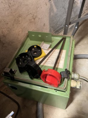
Back of the lathe
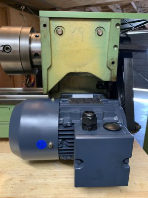
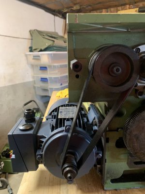
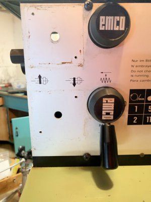
Here is what the front panel looks like now..
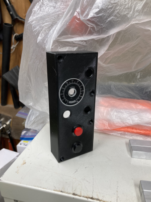
Thinking of getting someone to make me one of these for the VFD..
- Joined
- Oct 11, 2016
- Messages
- 4,005
@IamNotImportant since this is your first VFD, there's some stuff you need to know.
-If you can afford a VFD with an external braking resistor, that will help.
-It is much, much easier to put a VFD on a mill than on a lathe.
-No VFD is 'plug and play' You will be spending time configuring it. Be patient. the manual is very long, but many items you don't have to configure. The problem is that the manual won't tell you what the essentials are and which are not. If you have a digital version of your manual, some people here can help you with that.
-You need to know the current rating for your motor - it will be on the face plate.
-You have to set your VFD for Sensorless Vector Mode.
-You have to be sure you have the correct settings for the control buttons (we can cover that later)
-You need to set your acceleration and deceleration times. On my mills I use 5 seconds. Depending on you lathe and your VFD, this time will probably be more like 10 seconds+ I would start at 30 seconds and work my way down.. If your deceleration time is too short you can overload your VFD. It should be protected for this, but no need to trust that.
There's more but it is better if you view the videos first.
- Joined
- Nov 17, 2020
- Messages
- 1,723

