Lathe DRO

Just saw on TV, the F35 headsup helmet the pilot uses cost $400,000 ea!

That's reasonable, right?
Well since the display in the ski goggles is so much more affordable the reason the helmut costs 400k must be something to do with the 'special foam padding' ... no?
 
Frank Hoose has a video of a camera he has setup on the tailstock to help
him see when doing boring or internal threading operations. He has that
hooked up to a monitor next to the lathe. Not a heads up display, but
something to help with our old eyes... :D


My only concern (and maybe that is where a heads up display would help) is
I would be concerned that I would be too busy watching the screen and miss out
on something dangerous going on in front of me...
 
OK, it's not quite done, but time to post anyway.

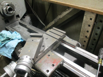
First the before picture.
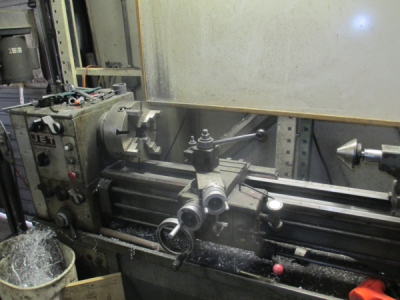
upload_2017-4-23_19-58-27.png

And the after installation picture. Still not quite back together, but I'm tired and need a break. :faint:
upload_2017-4-23_19-59-51.png


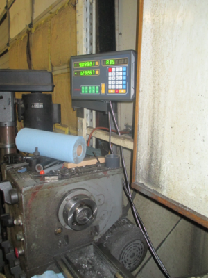
And the Readout.
upload_2017-4-23_20-0-48.png

OK, now for the fun stuff. The goal was to mount the scales so that they would not be in the path of flying chips, dropped objects, and not interfere with any operation. I don't like the normal mounting systems for most DROs. So this means burying the the scales and read heads inside the works.

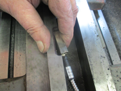
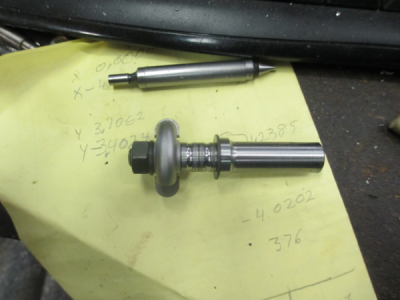
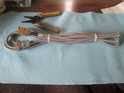
One of the magnetic read heads, 1 micron resolution.
upload_2017-4-23_20-7-52.png

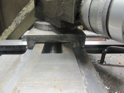
The before picture of the cross slide. The area above the dovetails is just clearance, not a bearing surface.
upload_2017-4-23_20-9-30.png

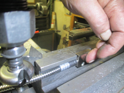
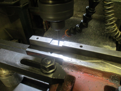
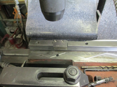
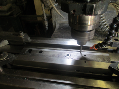
So milling a slot for the magnetic tape to sit in on the back of the cross slide. 1.6mm deep (mag tape thickness), 11 mm wide.
upload_2017-4-23_20-13-2.png

There were also no oil grooves on the cross slide, so I added some. 1/4 ball end mill, 0.015 deep. Whoever designed the oiling system on this lathe did not think it through very well, there was really no way for oil to get on the cross slide ways.
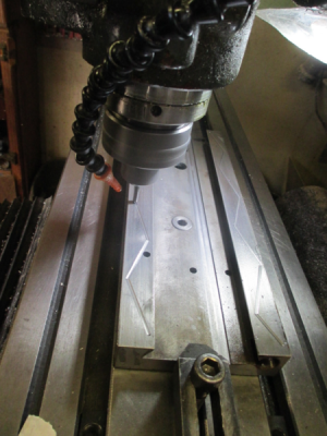
upload_2017-4-23_20-16-41.png

So now we have a slot for the mag tape.
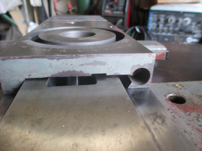
upload_2017-4-23_20-18-9.png

The next step is to mount the mag read head inside the carriage to line up with the mag tape. It needs to sit about here, more or less.
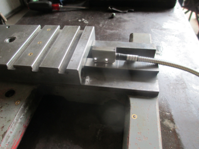
upload_2017-4-23_20-20-45.png

and another view
upload_2017-4-23_20-21-39.png

So clamping the carriage into the mill and locating the edges off of the cross slide, tells me where the mag read head needs to locate,
and that is about here
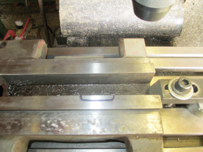
upload_2017-4-23_20-25-19.png

So chew out a pocket in the casting to mount the read head
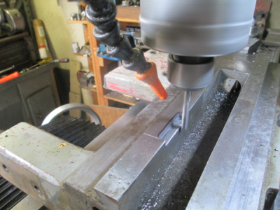
upload_2017-4-23_20-27-35.png


But we still have a little cable clearance problem. I can fix that ;)

upload_2017-4-23_20-27-49.png

One 3/16 convex radius router bit. One minor problem, I need to go deeper than the bearing will allow.
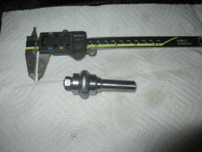
upload_2017-4-23_20-29-8.png

No lathe to make new spacers, so just break the bearings. Wrap in a heavy towel, and smack with a large hammer on a suitable solid surface. Forklift forks work well for this.:) Now you have a suitable spacer with a much smaller diameter.
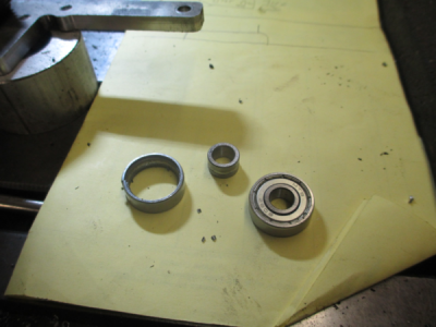
upload_2017-4-23_20-30-41.png

upload_2017-4-23_20-33-21.png

Now just carve out cable clearance. 500 RPM, 7 IPM, 0.010 step over.
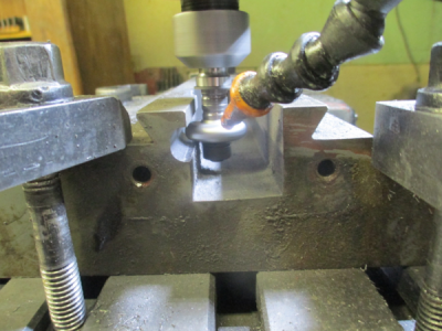
upload_2017-4-23_20-34-10.png

Now it fits properly.

upload_2017-4-23_20-35-51.png


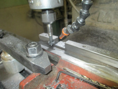
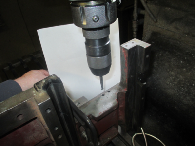
Then locate, drill & counterbore for the two M3 x 30mm mounting screws. I had to use a 1/4, 2 flute router bit to counterbore, the only thing I had that was the right size, and with enough length to counterbore 0.875 deep. I normally don't recommend an endmill in a drill chuck, but in this case I already had a 0.125 pilot hole through, and was very careful in my feeding.
upload_2017-4-23_20-39-19.png

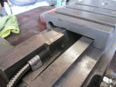
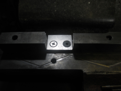
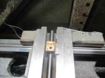
And there it is, mounted in place. You see why it is buried in the casting, not a heck of a lot of room between the nut and the read head.
upload_2017-4-23_20-45-24.png

OK, the X axis is done, now on to the Z axis :)
 
The Z axis

The back way is machined top, bottom and side. The top and bottom are bearing surfaces, but the side is not a bearing surface, and has clearance. A perfect place for the mag tape. The Z axis read head needs to mount in the back of the carriage to match up with the back way. So a little surgery is required on the back of the carriage. I also added oil grooves.

upload_2017-4-23_20-59-52.png

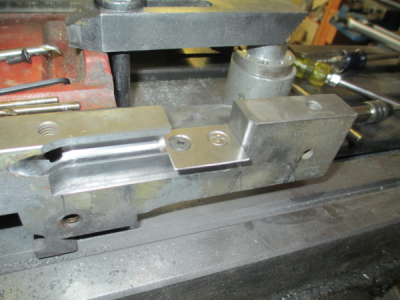
The read head is a bit wider than the back of the carriage, so a mounting tab was needed. I also needed to chew out cable clearance as I did on the X axis in the previous post. In addition, I needed to take out a bit more material to get tool clearance for the convex radius cutter because I had to go a bit deeper with the cut.
upload_2017-4-23_21-5-7.png

There wasn't quite enough clearance for the mag tape, so a T-slot cutter made quick work of adding a bit more clearance in the proper location. Normally I would not have this much stick out on the tool, but the shank had been turned down for clearance on another project and that's all I had to hang on to.
upload_2017-4-23_21-7-17.png

And there is the read head mounted in it's new home.
upload_2017-4-23_21-10-51.png

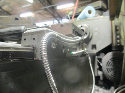
And a shot from the back showing the read head and tape installation. With the clearance slot cut in the carriage, it was pretty simple to get the tape to line up properly, just keep it in the slot.;)
upload_2017-4-23_21-13-41.png

So next is some cable management, and finish assembly. Should have that done in the morning. :)

upload_2017-4-23_21-1-32.png
 
A little update.

I have to say that when I opened the manual for the Ditron D100-2V DRO I was pleasantly surprised. It is well documented, and in readable English. Unexpected from a China manufacturer. It was written/translated by a native English speaker, and quite possibly someone with a machining background.:encourage:

The system works fine. I had to calibrate the DRO to match the read heads, took all of about 5 minutes. Seems to be very accurate and repeatable. The 1 micron scales are a little overkill, I probably don't need to read to 0.000039 inches. But who knows, maybe I'll get a job from NASA :grin:

Overall I'm very satisfied, and the lathe is ready to make chips again. :) On to the next project...............
 
Wow, next will be remote heads with solar power lithium . No cables to mess with. I like the route you took mounting and fixing the oiling problem , maybe its a good thing it made ya fix the lathe while upgrading. Nice job very nice.
 
Wow, next will be remote heads with solar power lithium . No cables to mess with. I like the route you took mounting and fixing the oiling problem , maybe its a good thing it made ya fix the lathe while upgrading. Nice job very nice.

Thank you for the kind words. :)
 
You make it look so easy! I would like to try one of those DROs. Please keep us posted on your experiences with it. Can it be ordered online?
Robert
 
Back
Top