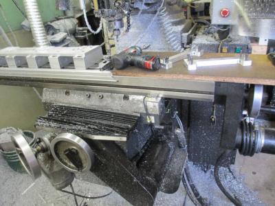
Lagunmatic CNC machine why not!

That makes much more sense. Thanks!
Yes, totally new to all this, and the language of the two is my first hurtle.
Pin 2 (signal input) is where you will connect the Kanalog JP11, DAC_10V for each axis. DAC means Digital to Analog Converter, and in this case +/- 10 Volt output
Pin 4 (signal common) is where you will connect the Kanalog JP11, GND
I can handle that tomorrow.
Another small step I should be working on?
 
Another small step I should be working on?
Not sure where you're at. But at this point you should preparing an I/O map. Much easier to make changes on paper or a computer than to rewire the system. Then when you start wiring, all you have to do is follow the map. The following is an example, I do these in a spreadsheet

FunctionGalil TermConnectorVoltageConnect toOrigional
INPUT
INPUT COMINCOM17I/OGND
Z LOCKOUTIN 1IN 1I/O24VSEL SWITCH
E-STOPIN 2IN 2I/O24VCP RELAY
PRIOR ACTIN 3IN 3I/O24V
IN 4IN 4I/O24V
IN 5IN 5I/O24V
IN 6IN 6I/O24V
IN 7IN 7I/O24V
IN 8IN 8I/O24V
COMMON5V30Ext I/O5V
JOG X-IN 2519Ext I/O5VJOY STICK 1
JOG X+IN 264Ext I/O5VJOY STICK 1
JOG Y-IN 2734Ext I/O5VJOY STICK 1
JOG Y+IN 2820Ext I/O5VJOY STICK 1
JOG Z-IN 295Ext I/O5VJOY STICK 2
JOG Z+IN 3035Ext I/O5VJOY STICK 2
IN 3121Ext I/O5V
IN 326Ext I/O5V
DIGITAL GNDGND33Ext I/O
DIGITAL GNDGND36Ext I/O
DIGITAL GNDGND39Ext I/O
DIGITAL GNDGND43Ext I/O
LSCOMLSCOMLSCOMI/O
LEFT LIMIT XFLXFLXI/OLMT SWITCH
RIGHT LIMIT XRLXRLXI/OLMT SWITCH
FRONT LIMIT YFLYFLYI/OLMT SWITCH
BACK LIMIT YRLYRLYI/OLMT SWITCH
TOP LIMIT ZFLZFLZI/OLMT SWITCH
BOTTOM LIMIT ZRLZRLZI/OLMT SWITCH
OUTPUT
OUTPUT PWROPWR11I/O24V
SPINDLE RUNOUT 141I/O24VRELAY
FLOOD COOLENTOUT 227I/O24VRELAY120VAC
MIST COOLENTOUT 312I/O24VSOLINOID24V
QUILL LOCKOUT 442I/O24VSOLINOID24V
COUNTER BALOUT 528I/O24VSOLINOID24V
 
Not sure where you're at.
Im lost....lol jk
Its starting to make a little sense.
I removed all the 3phase stuff in the box. It had a 3phase coolant pump that was missing. There was a little extra wiring and switches. then all the transformers for the stepdowns, that are now just wired to one of the 120 legs. Have my vfd installed and working for the spindle. I have the Kanalog board mounted. Thats its. Still have alot of wires hanging out that came from the Fagor control box. Computer is all hooked up running. I havent downloaded any software.
I found a wiring schematic on cnczone.com. I think this one is pretty relative. I just need to figure out what my encoders are for each axis and wire accordingly.
Making a spreadsheet seems like a great idea, but again I dont understand most of the verbiage. I figured I would be wiring and rewiring 4-5 times lol. Pretty sure making a spreadsheet will be really easy when Im done....lol
 

Attachments

  • Kanalog Connections(1).pdf
    77.4 KB · Views: 1
The schematic looks good.

I'm assuming the encoders are on the motors, so one caution, remove the belt from the motor until you're sure you have the motor under computer control. Those motors are powerful enough to do some mechanical damage if they run away. A runaway is very common when first setting up. Normally caused by having the encoder and motor running in opposite directions. You have a 50/50 shot at getting it correct the first time.

I don't know anything about the Kanalog setup, but there may be a way to change the direction in the program without rewiring. It there is a torque limit method available, set it very low to start with.
 
Oh yes, I have the belts off. I love carnage as much as the next guy, however I don't want to wreck the new toy.
 
Feel like Im getting somewhere now. lol
I wanted to find some info about the wiring for the encoders. Before I hooked them up wrong and fried something. Looked around for a few hours on how to figure out what wire is what on the encoders wasn't coming up with much useful info. Maybe if looked inside the fagor control box might give me a clue to what is at least positive and negative. Oh looky there! surprise, its labeled on the back of the old control box! How convenient, Still some odd verbiage.
So for the encoder I have
Red .....+5v
White .....A something?
Green .....B something?
Black ....Ov
black .....IO
Green..... Ground

i dont know what Ov stands for or what I0 stands for?

Im half way to knowing whats needed to make a spread sheet :)
 

Attachments

  • IMG_20191108_131129690.jpg
    IMG_20191108_131129690.jpg
    3.5 MB · Views: 11
Last edited:
A and B are the A and B channels, should go to A+ and B+ on the Kanalog board.

Pretty sure 0V means 0 volts or rather GND on the Kanalog board

I0 maybe means Index, but I don't fully understand the IO (I0?) The fact that the wire is black is also a bit confusing, could it be another color? Maybe black with a stripe of a different color?

Green ground, probably means the shield ground.

I would replace the encoders with differential output encoders (A, A\, B, B\), the single ended output can cause problems with electrical noise. The Kanalog board will accept differential input. In fact, you might want to install magnetic scales on the table and Z, better accuracy than having the encoder on the motor.


My X axis magnetic scale
1573248230810.png
 
All the axis have two black wires, one going to OV and one going to IO. I'll try and do some more digging and see if I can find some more info.
All this and I forgot to order a power supply for the kanalog board....
 
That is strange, the two black wires is a bit confusing. Maybe you can find a part number on the encoder itself, there may be some documentation available.
 
Back
Top