I've wanted a power feed for my mill for a long time and finally got around to getting one. Since I have a Millrite, nobody makes a bolt on kit, so I needed to make modifications to get it to work. I posted this here since the methods might be useful for other non-Bridgeport machines.
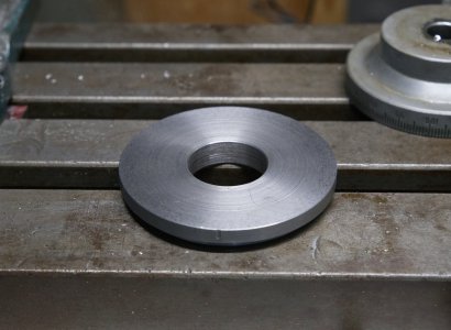
The first step was figuring out how I wanted to mount this, I read several other posts from Bob Korves and Tim9, as well as on YouTube, and used some of what they did, but did mine a bit differently. I considered making a new table bracket instead of modifying the existing end bracket, but decided to take the easier way first. First step was making an adapter plate to mount to the table bracket. The recess for the X axis dial in the table bracket looked to be ideal to have the plate fitted to, that way I did not need to machine the bottom of the recess in the table bracket flat. I made the round plate with a step that allowed the larger diameter to fit in the dial recess and the smaller diameter to give clearance to fit into the table bracket. I only took a picture of adapter plate from the larger face, the step is on the under side. I laid out the holes for mounting screws for the plate to the table bracket, and for the power feed to the plate.

Once the plate was finished, it was time to machine the leadscrew bearing flange in the bracket flat. The power feed drive gear needs to be restrained axially and since the leadscrew is straight until the threads instead of stepped like with the Bridgeport, there needs to be something that allows rotation of the leadscrew relative to the table bracket when everything is tightened up. I elected to install a thrust bearing between the table bracket and the bearing inner ring on the power feed. This required flattening the end bracket where the leadscrew is supported. Three holes were drilled and tapped in the table bracket for the adapter plate to mount to.


The bearing inner ring that is supplied with the power feed is the wrong size for the Burke 5/8" shaft, so I made a new bushing to serve as an inner ring. Since I am using the existing table bracket, the leadscrew is supported by the bracket and the bearing in the power feed is not doing anything, so any regular steel would work fine for that. The length of the new inner ring was taken as the distance from the thrust bearing to face of the power feed bracket where the bull gear sits. This leaves a bit of space between the bull gear and the inner ring for shims to get the ideal displacement for the gears.


The key slot in the bull gear is 1/8", the Woodruff key in the Burke leadscrew is 3/16", so I broached the larger key slot in the bull gear.

There is not enough shaft length on the leadscrew to mount the handle, some people make an extension for the leadscrew, I chose to make a stub shaft for the handle that fits into the bull gear hub. I then used a long bolt to tighten everything together. Instead of removing the leadscrew from the machine and drilling and tapping in my lathe, I made a drill bushing to do it in place, that was a mistake. The threads ended up a little bit crooked. I can still screw in the bolt, but it is not as easy as it should be. So much for taking a short cut.


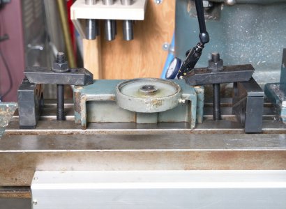
The dial for the X axis has a bore of 5/8", the bull gear uses the Bridgeport size dial bore of 1-5/16". Instead of boring out an original part, I just bought a Bridgeport dial on Ebay for about $45. This picture was before the new dial arrived.

Still yet to do is install limit switches. I mounted my DRO scale on the front of the machine so that I don't take up any Y axis travel. If mounted in the back, it limits the Y axis by however thick it is. I have a standard size scale, so it takes up about 1.5" of travel if mounted in the back. I just bought a Tegara 4" vise to replace my import one that was not doing a good job of holding stock flat, and that extends out the back by 13/16". I didn't buy the 5" vise due to how far it sticks out the back, which in hindsight would have been about the same as the scale would stick out, so no point in installing a standard thickness scale in the back. I might replace the scale with a slim scale and relocate it to the back of the table. My plan for now is to just make brackets to go into the T slot on the front of the table and mount limit switches on each end. The limit switches will hit the saddle when the table is at the end of its travel and shut the power feed off. I don't know if I care about having adjustable stops, so can change that as necessary.
I needed to shorten the Woodruff key a bit to fit with the number of shims required to offset the bull gear properly. There is still plenty of length that I am not worried about shearing it, but I could reduce the thickness of the adapter plate if it becomes and issue.
The first step was figuring out how I wanted to mount this, I read several other posts from Bob Korves and Tim9, as well as on YouTube, and used some of what they did, but did mine a bit differently. I considered making a new table bracket instead of modifying the existing end bracket, but decided to take the easier way first. First step was making an adapter plate to mount to the table bracket. The recess for the X axis dial in the table bracket looked to be ideal to have the plate fitted to, that way I did not need to machine the bottom of the recess in the table bracket flat. I made the round plate with a step that allowed the larger diameter to fit in the dial recess and the smaller diameter to give clearance to fit into the table bracket. I only took a picture of adapter plate from the larger face, the step is on the under side. I laid out the holes for mounting screws for the plate to the table bracket, and for the power feed to the plate.

Once the plate was finished, it was time to machine the leadscrew bearing flange in the bracket flat. The power feed drive gear needs to be restrained axially and since the leadscrew is straight until the threads instead of stepped like with the Bridgeport, there needs to be something that allows rotation of the leadscrew relative to the table bracket when everything is tightened up. I elected to install a thrust bearing between the table bracket and the bearing inner ring on the power feed. This required flattening the end bracket where the leadscrew is supported. Three holes were drilled and tapped in the table bracket for the adapter plate to mount to.


The bearing inner ring that is supplied with the power feed is the wrong size for the Burke 5/8" shaft, so I made a new bushing to serve as an inner ring. Since I am using the existing table bracket, the leadscrew is supported by the bracket and the bearing in the power feed is not doing anything, so any regular steel would work fine for that. The length of the new inner ring was taken as the distance from the thrust bearing to face of the power feed bracket where the bull gear sits. This leaves a bit of space between the bull gear and the inner ring for shims to get the ideal displacement for the gears.


The key slot in the bull gear is 1/8", the Woodruff key in the Burke leadscrew is 3/16", so I broached the larger key slot in the bull gear.

There is not enough shaft length on the leadscrew to mount the handle, some people make an extension for the leadscrew, I chose to make a stub shaft for the handle that fits into the bull gear hub. I then used a long bolt to tighten everything together. Instead of removing the leadscrew from the machine and drilling and tapping in my lathe, I made a drill bushing to do it in place, that was a mistake. The threads ended up a little bit crooked. I can still screw in the bolt, but it is not as easy as it should be. So much for taking a short cut.


The dial for the X axis has a bore of 5/8", the bull gear uses the Bridgeport size dial bore of 1-5/16". Instead of boring out an original part, I just bought a Bridgeport dial on Ebay for about $45. This picture was before the new dial arrived.

Still yet to do is install limit switches. I mounted my DRO scale on the front of the machine so that I don't take up any Y axis travel. If mounted in the back, it limits the Y axis by however thick it is. I have a standard size scale, so it takes up about 1.5" of travel if mounted in the back. I just bought a Tegara 4" vise to replace my import one that was not doing a good job of holding stock flat, and that extends out the back by 13/16". I didn't buy the 5" vise due to how far it sticks out the back, which in hindsight would have been about the same as the scale would stick out, so no point in installing a standard thickness scale in the back. I might replace the scale with a slim scale and relocate it to the back of the table. My plan for now is to just make brackets to go into the T slot on the front of the table and mount limit switches on each end. The limit switches will hit the saddle when the table is at the end of its travel and shut the power feed off. I don't know if I care about having adjustable stops, so can change that as necessary.
I needed to shorten the Woodruff key a bit to fit with the number of shims required to offset the bull gear properly. There is still plenty of length that I am not worried about shearing it, but I could reduce the thickness of the adapter plate if it becomes and issue.


