Improve finish and tolerance on a long thin rod?

It will be a lot simpler to just buy a linear shaft / guide rod like this kind. The finish and tolerance should meet your requirements. Cheap too. I have a bigger lathe but still I won't try to make it. Just not worthwhile.

Absolutely. Except the rod is "Invar", a special nickel / iron alloy that has roughly 1/10 the coefficient of thermal expansion of ordinary metals.

This little 0.25" by 36" rod cost over US $50, delivered. There are other suppliers, and other brands of such materials, some of which may (or may not) have better finishes, but the alternatives that I've found are far more expensive than that, even. I did buy a tight-tolerance standard steel rod for practice / mock-up purposes (costing 10 times less), but I'd like to make the best of this Invar rod if I can.

I sought that material in particular because I have a hobby interest in recreating historical scientific experiments. In this case, I'm interested in building a precision "gravity pendulum" (i.e., a "Kater's pendulum") that, starting in the early 1800's, and extending to the 1950's, was used to measure the strength of local gravity.

About 5-6 digits of precision is necessary for such measurements, and the use of Invar substantially reduces the need to compensate for expansion/contraction of the pendulum with temperature. The earliest such pendulums used brass (Invar hadn't been invented yet), and the last of the gravity pendulums used fused quartz for the pendulums, as that has even lower temperature coefficient, but that's considerably harder to get hold of and work with. Today local gravity is determined by measuring the acceleration of a falling object in a vacuum using laser interferometry.
I had a pretty good idea that's what you were up to. I guess the question is, how uniform does that invar rod need to be? Is there a way, in the spriit of RDM, that averages out the impact of rod nonuniformity on your measurement of G?
 
So the adjustment range will be over a relatively short distance at one end of the rod? This is a more doable task., You could turn the end to 6mm to establish a uniform sliding surface. Another thought would be to use a v groove and set screw to capture the weight. This would be independent of diameter, roundness, etc. of the rod.
Pendulum Bob.JPG
 
I had a pretty good idea that's what you were up to. I guess the question is, how uniform does that invar rod need to be? Is there a way, in the spriit of RDM, that averages out the impact of rod nonuniformity on your measurement of G?

RDM?

I have been presuming that minor non-uniformity in the rod will not significantly impact the measurement of g, at least if the bob weight is large. Although my target is to meet or exceed Kater's original level of accuracy, I'll be happy to come close. So for now, I'm more concerned about squareness and a fairly close, non-wobbling, sliding fit.

(By the way, it's "little g", meaning the local force of gravity due to the Earth, with "big G" being the universal gravitational constant that is independent of the Earth. The Cavendish experiment in the late 1700's was a magnificent tour-de-force that came remarkably close to the modern - and still woefully uncertain - estimate for that.)
 
Last edited:
So the adjustment range will be over a relatively short distance at one end of the rod? This is a more doable task., You could turn the end to 6mm to establish a uniform sliding surface. Another thought would be to use a v groove and set screw to capture the weight. This would be independent of diameter, roundness, etc. of the rod.
View attachment 401159

Yes, I've been contemplating reducing the extent of the adjustment range such that I can just machine a few inches on both sides - as you say to 6mm, for example. Some versions of gravity pendulums (e.g. Repsold-Bessel) have the bobs fixed, with any adjustment outside the knife pivots and bobs. For the moment, I'd prefer to try to keep the sliding, at least partially, as it's "safer" in a sense.

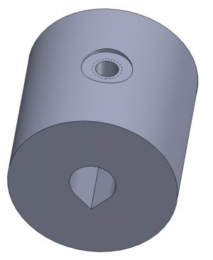
The V-groove approach would work to get around the rod's non-uniformity, but unfortunately it would break the symmetry of the balance, as it implies an offset from concentricity. I'd even expect to use 2 or 4 set-screws to try to balance them.

I'm planning to start with a mock-up to try some of these things out before using more expensive materials (ordinary steel and aluminum vs. Invar and brass, glass instead of sapphire...).
 
Last edited:
As I modeled it, the circle tangent to the v groove is concentric with the bob. the hole is larger than the shaft diameter so the gap could offset the missing material created by cutting the groove. As drawn, the center of mass is off the center of the bob by .02mm. (SolidWorks has the ability to analyze the model and provide the center of mass.)
 
As I modeled it, the circle tangent to the v groove is concentric with the bob. the hole is larger than the shaft diameter so the gap could offset the missing material created by cutting the groove. As drawn, the center of mass is off the center of the bob by .02mm. (SolidWorks has the ability to analyze the model and provide the center of mass.)
Oh, I see! Thanks. But as a machining newbie that looks a bit difficult. I think it's best for me to stick to simple concentric cylinders and bores, etc., and adapt or compromise my designs to use them.
 
Sherline offers a split bed pool cue lathe. A similar idea should work for a long spider, just need to add a mount on the back side of the headstock allowing you to place multiple supports for your stock. Since you aren't actually turning that material just preventing it from whipping I wouldn't expect that it requires a high degree of precision.

Sherline split bed pool cue lathe
Yes, I was thinking of 3-D printing a spider on a separate mount that can be clamped or some-such out at a distance, with a simple bushing or ball-bearing in it to keep friction from melting the plastic.
 
RDM?

I have been presuming that minor non-uniformity in the rod will not significantly impact the measurement of g, at least if the bob weight is large. Although my target is to meet or exceed Kater's original level of accuracy, I'll be happy to come close. So for now, I'm more concerned about squareness and a fairly close, non-wobbling, sliding fit.

(By the way, it's "little g", meaning the local force of gravity due to the Earth, with "big G" being the universal gravitational constant that is independent of the Earth. The Cavendish experiment in the late 1700's was a magnificent tour-de-force that came remarkably close to the modern - and still woefully uncertain - estimate for that.)
RDM stands for :Rollie's Dad's Method and is a technique for measuring alignment on a spindle (lathe or mill) that compensates for a non-ideal test rod. When I said "in the spirit of", I just meant that there might be some way to perform your determination of "g" in such a way that nonuniformities in the invar rod would cancel out. Perhaps by turning the rod 180 degrees and repeating the experiment, then taking the average (for example).
 
Back
Top