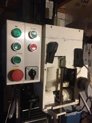
Ideas for Quill Stop for PM932/940 mills with power downfeed

I have been doing more brainstorming while scouring the internet looking for alternatives and materials to use and going through my materials on hand to see if I can make this stop with what I have. I have pretty much ditched the idea of using the 1/2-20 threaded rod in-line with the quill because I do not see there being enough vertical travel. I want there to be a solid flat surface for the quill stop but that will take up more of the already limited travel.
What I don't like about the PDF heads is that the hole for the quill depth stop is very close to the edge of the casting although I am finding the location and size of this hole vary depending on when it was built and the name on the machine. For instance Stefan's Optimum branded mill which was built many years ago has a smaller 16MM bore located deeper into the head and there is a boss that protrudes below the base of the head casting. The same goes for the slotted hole on my quill ring. The slot is cut close to the edge of the face and this leaves little material for strength so I will be adding a steel insert (basically the same design as darkzero's) that sits in the pocket of the quill ring after I machine the rough casting.
I am pretty much set on building a quill stop very much like Stefan's and I think I am also going to add a dial indicator as well. My though is that although I already have a digital readout to assist in monitoring the depth of the quill it wont work with the depth stop as accurately. I have thought about ditching the Z-axis scale for the head height and cutting down the scale and putting it on the depth stop. I feel that the Z-axis scale will get very little use but somehow I think I will regret it so this option alone has slowed down my progress because I am trying to figure the pro's and con's of this option.
What I am in the process of doing right now is cleaning up the rough casting inside the head where I would I am going to be making a positive stop for the adjustable stop. I want to keep it as short as possible and there are tall flashings that need to be removed. I will keep this updated with my future progress.
@9t8z28 I have PM932M and I'm looking to do the same thing.

What's the progress or your final solution?
 
Ok here is what I got accomplished tonight
I ground and filed down the rough flashing of the headstock. I also milled out the pocket in the quill ring using a 1/4” 4 flute EM with a .030” radius. I removed about .045” off the sides and about .070” deep to clean it up. Lastly I mocked up the the 1/2” shaft and took a photo with the quill retracted and extended. I decided that a dial indicator will not work because there is just not enough room and the more I think about it having a quill dro and dial indicator is overkill. I can check my depth with the quill dro and if I make an adjustable stop I can still use gauge blocks if I really wanted to. Here are some photos.


A9C640E1-2A80-471E-A563-7011A7DCA024.jpeg

265946BF-9ACA-462A-96D5-F1365E924AF1.jpeg

13DFF1A0-CFED-4FC9-9DF5-E525D45A5908.jpeg
 
Darkzero I don’t know how I missed it, I must’ve been so excited to see the thread you started on mods to your PM45 mill that I totally missed that your mill doesnt have the powerbox on the left side of the head. I wouldn’t be able to use your style quill depth stop if I wanted to
 

Attachments

  • D249999F-0909-48B0-8BE5-3013AE61A743.jpeg
    D249999F-0909-48B0-8BE5-3013AE61A743.jpeg
    910.6 KB · Views: 206
Yeah the PM45 did not come with a power head (Z) so my control box is very basic, just the spindle fwd/rev switch & a switch for the coolant pump. My PM45 did not come with a factory quill DRO either so mine did not come with a quill bracket. Luckily & thankfully when I asked Matt to purchase a quill bracket he sent one to me for free. The last of the PM45s did come with a quill DRO but still no power Z.
 
Update: I started the quill rod lock (made from 1” diam 01) to make sure it would fit with the quill rod retracted. Then I ordered a 1” long Oilite bronze bushing and 1/2” hardened and ground linear shaft with the last 2” of length tempered back soft. I then made the sleeve that will go into the base of the head and house the bushing. I used 1.625” diam 4140 PH. Next is to make the bracket that will hold the linear shaft to the quill ring. Anybody have any ideas on how to attach the quill rod to the bracket? I want to make sure its a solid joint. I though about threading it or press fit?
here are some photos of progress..

40A95E2D-D959-4621-82F7-91AA81848BE5.jpeg

13C4FD65-0728-486D-B84B-3EE9A15F8F48.jpeg

the bushing still needs to be pressed into the housing
C74624E8-4B0E-4221-A9D6-66F0245888CC.jpeg

9A33C744-39EC-4752-A6B0-14A464AAED40.jpeg
 
I can't believe it's been since August since I started this project. Sorry for the delay! Quite a bit has changed since I last posted and I didn't realize that I had previously posted the same info. For some reason the forum wasn't showing me all of my posts. Oh well. Hopefully I do not confuse anyone. Sometimes I question my ideas and change things up before I turn my thoughts into metal. Other than breaking my toe and constantly fixing and maintaining my cars and trucks, I have no excuse for being lazy during this pandemic!

I'm basically done fabbing the quill stop other than cutting a vertical slot in the front cover and adding a boxed shield behind the quill rod to keep swarf from entering the PDF gearbox and lastly remounting the DRO.
I was originally going to use a 1/2-20 threaded rod and a Morton quick quill stop but I soon found that there wasn't going to be enough room if I wanted to keep the 5"+ of quill travel, hence why I decided to go with a 1/2" linear shaft and make my own depth stop.

The first thing I did was remove the factory cast iron quill ring and clean up the pocket on the underside. I used a 1/4" end mill and took out only enough material to give me a nice flat/square pocket to work with that would also be perpendicular to the bore of the quill ring.
QUILL1.JPG


QUILL2.JPG


Next, I made the quill shaft clamp and quill shaft headstock sleeve. I used 01 tool steel for both parts since I figured they would both be in repeated contact with each other and therefore would definitely need to be heat treated.

Offset Boring of the quill shaft clamp
QUILL3.JPG

The parted quill shaft clamp.
QUILL4.JPG


Offset turning and boring of the quill shaft headstock sleeve
QULL5.JPG


Test fitting the oilite bearing
QUILL6.JPG


QUILL8.JPG


Checking the fit and alignment
QUILL7.JPG


QUILL9.JPG

Continued in Next Post..........
 
Last edited:
Next step was making the steel block to fit tightly in the quill ring. I used 01 again, (I have a ton of it so might as well use it) but i did not see a need to heat treat it.
QUILL10.JPG


I then bored to a half thou under 1/2" for the quill rod and drilled/tapped holes for mounting the block to the quill ring.

After some more test fitting and brainstorming I got around to slotting the quill lock and drilled and tapped for 6MM thread. Sorry no pics. Next was surface grinding the quill shaft clamp and quill shaft headstock sleeve. I did a quick job of getting them flat and really saw no need for a spectacular surface finish.

QUILL11.JPG


The last step was fitting the finished parts to the mill. I had to do some minor fitting to assure the quill rod traversed parallel to the quill. The fit of the quill rod and bearing was a tight fit so I had to get it under half a thou or else it would bind and restrict the quill from retracting all the way. Also instead of pressing the quill shaft headstock sleeve into the head of the mill decided to enlarge the hole and glue it in. I considered using JB Weld to glue it in but I wanted something that I was sure would stand up to oils, vibration, and impact. After speaking with McMaster-Carr I decided on an epoxy called Scotch Weld which is specifically designed for bonding steel together. It was expensive but worth it. It has a thick consistency which would not run when applied to a vertical surface and set within 10 minutes.

(Notes for below pic)
Take notice to the quill rod. If it needed to be any longer it would not have cleared the casting. The factory hole in the headstock for the PM-932 (non PDF models) is centered in the base for a threaded rod depth stop. The components of a sliding depth stop need to be planned and measured accurately or interference would be inevitable.
ALSO Notice the paper towel jammed in the corner of the headstock. Apparently my mill seeps gear oil :( and I didn't want it soaking into the uncured epoxy.
QUILL12.JPG


QUILL13.JPG


QUILL14.JPG


QUILL15.JPG


Conclusion: I am glad I took my time making sure everything fit inside of the headstock because when the quill stop setup is in the retracted position I literally have .020"to .040" of clearance from the top of the rod and lock to the headstock casting. Besides being able to set precise depths without using the wonky powerfeed depth stop, I can already tell that the quill assembly while unlocked is tighter and has less tendency to want to rock and rotate in its bore. With the added rigidity I think I should notice a difference when plunge milling and climb milling and the fact that the quill cant rock in its bore I should also have greater accuracy all around.
Last thoughts: I am not sure if I am crazy about the locking handle. Maybe a longer handle with more protrusion or does anyone have a different idea for locking it that would be quick and easy?
Thanks for all who commented and shared their designs and ideas.
 
Last edited:
Heres the final product. A made a shield to go around the complete quill stop to keep swarf from entering the PDF gearbox. I took a piece of .040” aluminum sheet, bent it to shape and secured it to the front cover. Hopefully I dont get anymore addition vibrations. Now I just need to find a way to get rid of the red “caution change speed with the machine stopped” Warning label. Let me know what you think or what I could have done differently

A54AB04A-1DD9-455D-90C1-9F304F686668.jpeg
 
Back
Top