- Joined
- Jan 31, 2016
- Messages
- 12,916
I fully understand all that , but this is a band saw . You lift it to the top with flow control open and throttle it down as you reach your material . Just vent the upper portion of the cylinder .
I have wanted a hydraulic dampener for the 4x6 band saw since I got it. I've seen the various builds here and also seen the complete unit for sale online for $180. I have sourced the parts and it appears I could almost double the cost of the saw I am not opposed to it but if I could do it cheaper that would be a plus in my book. Not to mention I could use the practice in fabricating and machine work.
So I did what any home shop machinist would do, I went to the scrap pile, I mean stock of pristine raw materials waiting to be freed from prior forms which seemed useless.
What I found was a length of 1.25" OD x 1" ID aluminum of undetermined alloy. In its' prior life it was a display built for wind chimes and is painted black and had some holes at each end and in the middle but with several feet of useful stock in between. Bingo, there is the cylinder for the hydraulic cylinder. I lop 10 inches of it off using the saw which will be the recipient of this project.
Then I have some 1.25" steel shaft which will become the end caps and piston. At this point 85% of the mass of the thing is decided upon but now my scrap pile is exhausted of future HC components and I have to go shopping. I do some rough measuring and sketch out a "plan" on a junk mail envelope.
I set off with the 3 hellians in tow to the local hardware store. I seek parts while they seek toys and torment the employees. I quickly find a 3/8"x10 zinc plated grade 2 bolt which appears by all measures to be hiding a HC rod in nearly plain sight. Shortly thereafter I find some o-rings which judging by my crude measurements will effectively seal the end caps, the piston and the rod. More likely of course is they will direct slow leaks of hydraulic fluid into streams which will rival a waterjet in their ability to soak everything in sight.
I gather up the kids and leave the frazzled employees to restock the toy aisle which by all appearance was struck by a mid-December tornado outbreak. Sum total bill, $3.08. Hearing the weeping from the toy aisle, priceless.
At home I had a little time before shower and bed time for the wrecking crew to get a little chip making in. So I popped a DVD in the player and hit the play button on the kids' favorite movie. The 1987 classic by Stanley Kubrick, "Full Metal Jacket". I retired to the basement where I could hear Gunnery Sergeant Hartman berating the recruits in an artistic display of profanity and the giggles of the 12, 7 and 4 year olds glued to the screen and hanging on every syllable of the profane poetry. Really, they were watching Paw Patrol, FMJ is what the wife accuses me of letting them watch when she goes out to drink wine with the "ladies" from the hospital. I head to the basement while they are occupied with the TV and G-rated programming.
First I true up the ends of the cylinder on the lathe. The interior walls seem to be fairly smooth and consistently measures 1.05" with the caliper. Since I have no way of honing the interior of the tube, smooth and consistent is a good thing. Then I move on to start the piston. I face off the stock and turn the OD down to 1.045. A little polishing with emery and it looks pretty good and slides freely into the tube with no contact and very slightly perceptible play. I then use a parting tool to cut a groove for an o-ring. The o-rings are 1" OD and .1" thick so I need to give them just the right depth to sit in the groove and fill the tube but not bind. My calculations are the groove needs to be .093 deep to create a seal which can move freely with the o-ring. I cut the groove to .090 and test it. I find it binds so go in and take .003 more and test again only to find it fits just like the piston without the o-ring did, freely with barely perceptible play.
Every piston needs 2 rings at least by my judgement so I cut another groove .090 deep and test it again, this time using a little oil on the o-ring and find it slides smooth. I drill the piston for the rod and then go to part it off and promptly break the parting tool. "Shat" and from behind me I hear a little 4 year old voice, "shat". I turn and there is my 4 year old grinning wearing his goggles, "whatcha doing Daddy?" "Don't tell your mom I said that." "Said what?" He is a good kid or has a very short memory but at least he wears his PPE. I let him watch as I change from a carbide parting tool to a HSS. I creep it deeper and deeper and am within .05 of parting off when "craaaaaacrunchhhh" it grabs and snaps off. The 4 year old says "shat" and laughs. It is bath time, if I can't wash his mouth out with soap I can at least try to keep the external bits of him clean.
Once the little ones were clean on the outside and asleep I finished the parting off and did a test fit. With just my hand over the end of the tube I can build pressure, time will tell if I end up with something that will hold hydraulic fluid but even if I don't at least I am learning and so is the 4 year old.
To be continued.
There is also a good write-up on building a cheap hydraulic cylinder for an HFT 4X6 in Machinist's Workshop 10-2015.Check the November/December 2018 and January/February issues of Home Shop Machinist. I've written up how to build a downfeed hydraulic cylinder based on a screen door closer. Total cost about $25-50.


I mention that article, as well as one by Mike Cox (http://mikesworkshop.weebly.com/bandsaw-hydraulic-cylinder.html) in my article. Both are very good (as are lots of others scattered across the interwebs). I made use of Mike's concept of incorporating the needle valve within the piston when I designed my downfeed. DIY cylinders, such as yours, are indeed nice. I just took the quick-and-lazy approach when I made use of a screen door closer.There is also a good write-up on building a cheap hydraulic cylinder for an HFT 4X6 in Machinist's Workshop 10-2015.
Plus, Youtube creator Haligan142 did three videos on that same build, to include some improvements.
There is also a good write-up on building a cheap hydraulic cylinder for an HFT 4X6 in Machinist's Workshop 10-2015.
Plus, Youtube creator Haligan142 did three videos on that same build, to include some improvements.
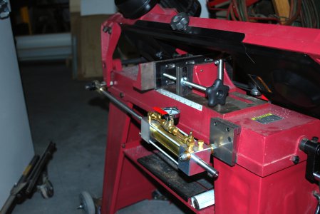
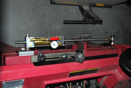
FWIW, I built the Machinist's Workshop unit for my HFT 4X6, and added a pressure gauge, which I use all the time for precise downfeed control (or dampening). I did use double o-ring rod and piston seals using Hi-Tech Seals' O-Ring Design Guide.
View attachment 307920View attachment 307921
I have the HFT 4X6 model. With the cylinder needle valve closed and the ball valve open, the pressure varies from 0 psig when the blade is at about 45 degrees from vertical to about 90 psig right before the blade hits the work (the near horizontal position).Bill
What kind of pressure do you typically see on your gauge?
Nice build btw
