How Would You Center This Under The Spindle?

tomw

Registered
Registered
Joined
Jan 24, 2015
Messages
239
Dear All,

This is a continuation of this thread.

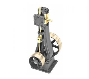
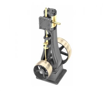
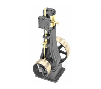
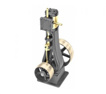
The project is to build steam engine #5 from PM Research:
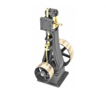
STEAM-ENGINE-5-450x400.jpg

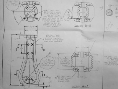
The part I am currently working on is the main frame. The drawing is below.
P2080055.jpg

All the circled dimensions are high tolerance.

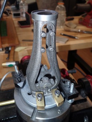
Here is a shot of the part during machining the top bore and it's relief:
P2080054.jpg

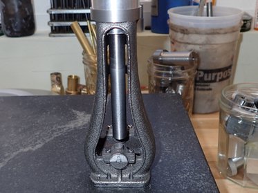
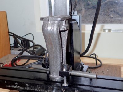
My question, now more broadly defined, is how would you go about centering this:
PC250010.jpg

under the spindle to machine the inner surfaces of the journal bosses.

The inner distance between boss surfaces has a tolerance of ±.005, and they need to be square to the crank axis. See this drawing below:
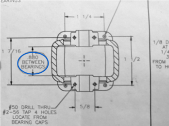
Boss Highlight.png

I have already machined the central bore and relief on the top of the frame (bottom in the set up picture above) and the crankshaft journals. My goal is to use that bore plus the crankshaft as a reference to machine the inner surfaces of the crank journals.

So, hints, tips and tricks will be much appreciated.

And, the winner gets a prize. Not from me, mind you, but if you live long enough you eventually get a prize.

I am missing something, that I know. Unfortunately, it is a known unknown of an enigma.

Thank you all for your help and suggestions.

Cheers,

Tom
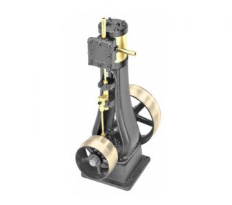
STEAM-ENGINE-5-450x400.jpg

STEAM-ENGINE-5-450x400.jpg

STEAM-ENGINE-5-450x400.jpg

STEAM-ENGINE-5-450x400.jpg

STEAM-ENGINE-5-450x400.jpg
 
If you make a plug for the bore with a big flange of a reasonable height under it and stand that on the mill table you might be able to get an indicator mounted in the spindle to sweep around it.

Stuart
 
I forgot to mention, I am using a Sherline 5400 mill with an extended column. Small is beautiful, I am told regularly. Probably because I am overweight.
 
I would have made a plug that fit the bore well and had a flange to clamp to the table. Then if I did not have enough travel to get an indicator down to the plug to center it. I would make a rod to lower the indicator enough so I could. Then put the part on have at it.
 
I would have made a plug that fit the bore well and had a flange to clamp to the table. Then if I did not have enough travel to get an indicator down to the plug to center it. I would make a rod to lower the indicator enough so I could. Then put the part on have at it.

If their was a hole in the centre of the top hat type plug , that could be held with a t nut and indicated and the part mounted on the upstand of the top hat.

Stuart
 
As said, use a plug for center. Use a drill blank and indicator for square. And use an adjustable parallel and micrometer for measuring the 0.880”…Dave
 
If you make plug put a center hole in it as well that fits a pin snug. That way you can use the plug with pin to locate center when part is laying down for any side holes just by indicating pin center.
 
All great suggestions.

I did make a plug and pin to bore to find the center of the journal bores for the crankshaft. I just can't find a way to indicate from it when vertical.

P2120069.jpg


If I make a plug that is tall enough to be both reached by an indicator, and have enough room around it to sweep, the plug will interfere with the milling operation. Unless I am not understanding what folks are suggesting. Which is likely.

The piece is a little over 7 inches tall, and the bore through the top is 3/4". The journals are about 7/8" from the bottom. The area available to sweep an indicator becomes small quickly below that point.

However, based on your suggestions, I am thinking of doing the following:

1) make a tight fitting plug with a concentric flange that just fits inside the recessed area. The flange will be about 1/8" thick. This is like the plug pictured above, but with a much shorter flange and without the long pin.
2) center drill a clearance a 10/32 SHCS hole in the plug
3) mount the plug to a tooling plate, mount the plate to the mill table
4) indicate in the plug at spindle center
5) mount the frame onto the plug and get it all square and level. Then clamp the whole thing securely (somehow).

Would this work, or would I introduce way to much slop?

BTW, I earlier stated the tolerance for journal to journal incorrectly It is .01, not .005. I didn't understand my notes. Sorry.

Thanks,

Tom
 
Last edited:
If the plug has a rim or through hole to hold it down then you indicate the plug before mounting the part. The part is then not in the way and will be on center of the plug when put on plug and clamped down. Once you have the part clamped on and squared up then you can mill the other end to the print because you are on center of the parts bore. Squaring the part up is a simple matter of indicating the edge of the part in the x, y direction. Just remember to set dials to O before moving table. If you can't indicate the part with indicator in spindle then indicate it to edge of the table. This should get it straight enough for milling.
 
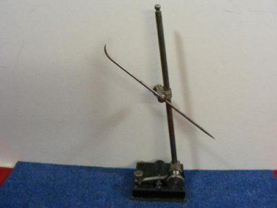
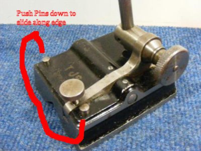
to indicate along edge of table for squareness use the indicator holder shown below.
starret base.jpg starret base 2.jpg
 
Back
Top