How to hold and drill 2 holes on a single diameter of a cylinder (thick tube actually)

dbb-the-bruce

Dave
H-M Lifetime Diamond Member
Joined
Feb 28, 2019
Messages
530
Another not so easy hold, locate and drill job.

On my mill, I need accurately drill two holes on the same diameter (opposite each other, same distance from center).

First thing I can't figure out. Hold the cylinder perfectly vertical - axis accurately aligned to Z axis / spindle of mill. Not only how to hold it but how to confirm that it is vertical. I have a dial gage and indicator. Mount to spindle and sweep the sides of the cylinder?

If I can measure the sides of the cylinder in X & Y I can sweep them in Z and make sure it vertical along with accurately finding the diameter and then drilling appropriate distance from center.

So it's really two questions, how do I hold this thing and then how do I measure it?

I also have a wiggler but that seems like a non-starter because I'd be trying to find the high spot on the cylinder. Maybe use the wiggler multiple times in X and Y and keep updating the centerline in X & Y. That could work to find the center of the top face. I'd still need to sweep the sides for vertical.

So maybe I can handle the measurement / indicating.

Holding it in place is still an issue.
Any helpful hints welcome!

-Dave
 
I'm having a bit of difficulty wrapping my head around exactly what you are doing. Maybe a picture of your proposed setup, the workpiece, or a drawing would be helpful.
 
Sounds like a job for a Hartford head or what we call a super spacer .
 
I’d probably use a v-block that I trust to get the cylinder vertical. You could definitely sweep along Z with the spindle-mounted indicator (on both an x- and y-facing surface) as you propose. I’d use a standard edge finder and do it iteratively (as you propose) for location on the end of the cylinder. What tolerances are you working to?

A vertical indexing head could be used to spin the part 180° for the second hole if they are the same radial distance from center.
 
If I understand you, you want to drill holes in the end of the piece, like we would on a lathe. You would use a 90 degree angle plate bolted to the mill. Put a vee block between it and the rod and clamp the assembly to the angle plate. you will have a lot of jiggling and shimming to get the Z perfect. I would use a DTI first on the Z and then on the X-Y to get center.

If you don't have the angle plate and vee, I would use the biggest piece of angle iron I could find and mill a good size slot on one side to give you 2 points of contact and then clamp to it. As above a picture and some dimension would be helpful.
 
Not knowing what your tool box consists of , but here is a great way of doing pipe work . Lay rods in the vees on your mill table and use a right angle head on the mill . I made up a couple sets of blocks for just this type of work . :encourage:
 
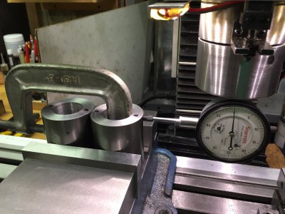
Ok, so not so bad. Biggest issue is what I have to work with. 2" cylinders - I don't have vee blocks that big and I think they would just get in the way. This actually worked as a good approach because I need to drill both pieces. The dots are roughly where the holes are going.

The C-Clamp is not super torqued, just enough to insure that the cylinders stay in contact. Have both in the vice at once make the vise work with even pressure and I need to do both anyway. Put a flat bottom on the dial gauge so exact center line is not critical, close enough works. The cylinders are sitting on parallels and were faced and bored on the lathe so the faces are actually quite square. About of .001 variation and it's not one end or the other - it's the rough stock. I should have turned the outsides while it was on the lathe.

Will tighten the vise and then remove the clamp so I can check the other side. All of this assumes that my vice jaw faces are vertical - they are right? (I've never checked them).

Will use a wiggler to establish the center line (X axis, Y=0). Can check that bunch of times just to be sure. Wiggler should also not be too sensitive to being dead center on the high spot of the outside of the cylinder - particularly if I lock X while doing it.

What do you think?

IMG_4309.JPG
 
Use the wiggler to find the center between the two jaws. (Between the two cylinders)

(It doesn't appear that your indicator axis is parallel the X axis) And even if it were, is it on center of the spindle?
 
If the IDs are bored to a face , just clamp the cylinder down on the machined face on the tale and indicate the bore for C/L . Move off in x or y for your hole spacing . A little trick for doing more than one is to cut out a V shape in a scrap piece and bolt it down to the table against your indicated part . Slide extra parts into the V and bolt down . This will generally get you within a few thou for quick reference .
 
Back
Top