- Joined
- Feb 4, 2013
- Messages
- 103


This is a plastic handle for a power disconnect cabinet that will be mounted outside and will be fully exposed to the sun and rain (i.e. not under a roof eve, etc). Therefore, I do not see it surviving very long, even if it IS intended for outdoor use. But more importantly, the disconnect box will be mounted to a restored 1932 airways beacon tower and the red & black plastic handle looks totally out of place. So I've decided to make a replacement handle out of aluminum.
The tricky part is going to be cutting the splined hole in the new handle to accept the splined shaft sticking out of the box. (The shaft rotates to open and close the disconnect switch.) Being that this is a low duty-cycle function (little use, limited rotation angle, and a very light force required), the fit of the new handle to the existing spline doesn't have to be to NASA specifications. I figure to make my new handle in two pieces: the splined end, and the handle itself (both, of which, can then be turned on my lathe) and then weld the two pieces together.
To create the seven splines, I plan to form them by simply drilling seven holes. (This piece is small, about 1.5" OD and the hole will be blind so broaching or filing them is out.) After drilling the splines, I'll then drill the larger center hole. Yes, I know it won't be perfect but I'm sure it'll suit my needs.
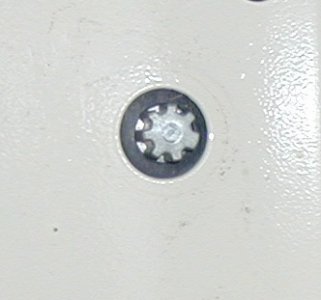
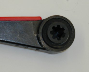
My question to y'all is how to lay out the splines (holes). If you'll look carefully at the pictures, you'll notice that six of the splines are a set width. However, there is one fat spline (at the 4 o'clock position in the pictures) that allows the handle to slide onto the shaft at only one azimuth. While the six smaller splines are equally spaced, this fatter indexing spline throws a curve into laying out all of the splines. In other words, the fat spline isn't conveniently twice the width of the smaller splines. (Is it clear what I'm trying to describe here?)
Sooooooo, any suggestions?
TIA
Harvey
