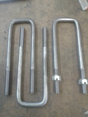
Help with U-bolts needed

Yes the true bend lines can be calculated and every material will have a different bend factor to account for the differences in compressive and tensile strengths. I have never worked at any 2 shops that used the same bend factors even for the same materials. Every shop that I have been at had to do the test coupons to determine what works for them. Once you have the numbers to work with your setup, it is not that hard to hold a few thou on bend tolerance.

If you change your bend fixture or material you need to do new coupons.

The basic formula is (bend factor X material thickness) + (1.57 X inside bend Radius) This gives the amout of flat material consumed in a 90° bend, you then just add up all of the straight lengths to get the blank length.
To get the bend factor you have to do the coupon to measure just how much material was used in the bend and then simple algebra to solve for bend factor.
 
Last edited:
To get the bend factor you have to do the coupon to measure just how much material was used in the bend and then simple algebra to solve for bend factor.
Why do you call it a coupon? Sorry if it is a stupid question. Can you give an example of the algebra part,I have math avoiding issues :big grin:
 
Little off topic but when I was getting my E7018 certification for bridge & crane welding, those pieces of plate a person welds are cut up into pieces called coupons.
Then they are machined flat and then bent to make sure they will bend and not break.
Kinda over simplified but that’s how it was done aeons ago when I certified.
 
Is this bend factor MULTIPLIED by material thickness and the 1.57, is that in inches or just a number?
Yes the bend factor is multiplied by material thickness or in this case Diameter.

The 1.57 is 1/2 of PI.

I have no idea why it is called a coupon, but that is what everyone has called it for the last 40 years so I do to.
This same thing works for Sheet or plate also.

BF = Bend Factor
R = Inside bend radius (not the tool R but the actual R of the material.)
BL = Bend Length.
T = Material thickness or Diameter.

So the formula is BL = (BF X R) + (1.57 X T)

So to calculate the BF it would be
BF = (BL - (1.57R)) ÷ T
Thanks for you help. I appreciate it.
 
OK, just spitballing here ... I can imagine that inconsistent length results might well be due to the workpiece slipping (inconsistently) as it's bent. One possible solution - clamp a Kant-Twist on the workpiece, up against the right-hand post of the bender. That sould at least keep the bar from slipping while it's being bent.
WINNER, WINNER, CHICKEN DINNER.
I Use a tube flare bar from an old tube flaring set to stop the material from moving.
 
I made the "coupon" today and showed it to the customer and he was happy ,but at the end of the day I went a whole different way of bending. But all of you will have to wait in susspence till Monday. I will post pics of the procedure then. Didn't have time for the other three today.
 
Well I saw a video of a guy making n round u-bolt with a jig an die,so I thought why not try that,looked simple enough.

I made a die with a 57mm width a radius of some sort,round about 14mm,and hardened it. Also a jig with an inside diameter around 85mm which is the outside measurement of the finnished U-bolt. I put two small notches on the die just to center the rod with the die.
20210215_112502.jpg20210215_100429.jpg20210215_100451.jpg20210215_100442.jpg
Put the setup in the press all centered up and press. Then all it took was to bring the legs closer and there it was.
20210215_112119.jpg20210215_110848.jpg20210215_110248.jpg20210215_110318.jpg20210215_110336.jpg
The one on the right was the sample, I just needed to make the legs longer. The customer took one to check if it fits and he was happy. It goes on a Model T Ford.
20210215_112412.jpg20210215_112338.jpg
Thanks everyone who helped,and don't worry, the information given will be used in the future.

Thanks
Michael.
 

Attachments

  • 20210215_112329.jpg
    20210215_112329.jpg
    551.9 KB · Views: 1
Back
Top