Help With Burke #4

Glenn Brooks

H-M Supporter - Gold Member
H-M Supporter Gold Member
Joined
Nov 14, 2014
Messages
851
image.jpeg image.jpg image.jpeg Hello all,

Note: I went back out and figured out how the assembly goes back together - found a couple of threaded nuts in a box of loose parts that fit the lead screw - ran them in tight against the inside of the casting so no play with the lead screw. Also reversed the auto feed lever to hold the arm engaged . So looks like good to Go. love the simplicity!

Tomorrow will work on connecting the drive linkage to the auto feed...


Having a couple of problems figuring out how the table assembly goes back together on my Burke #4. I purchased the machine partially disassembled so don't know if any parts are missing.

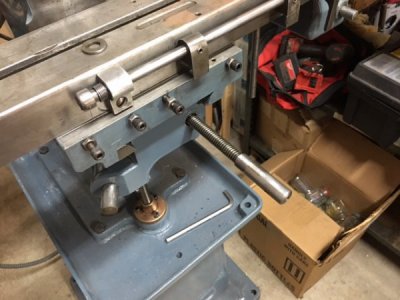
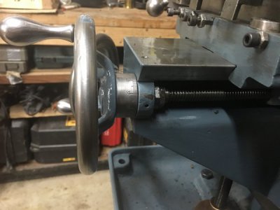
My first problem is how to secure the y axis lead screw against the bushing, so it pushes and pulls the table along the knee when one turns the hand wheel. In the first photo, the leadscrew has a thread pattern, but no sign of a shoulder, pin, or method to hold it in place after inserted into the bushing in the knee. Of course the army Burke manual shows no internals...


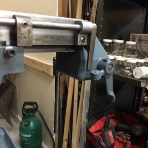
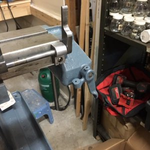
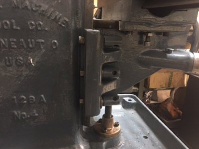
Second issue, is how does the auto feed lever on the right end end of the table hold the the x axis leadscrew gears in place to feed the table? Here are the parts I have installed - in what I assume are the correct locations...

Iam off searching for an exploded parts list, but so far no success...

Thanks much for any suggestions anyone can offer!

Regards
Glenn
 
Last edited:
What does the other end of the Y lead screw look like? The thrust bearing might be on that end. Also looks like there is a shoulder at the end of the threads in the picture.
 
I made a new lead screw for the y axis on my Burke 4 ( but it is probably older). I don't look like yours. I have some diagrams on my computer but can't get online with it until Wednesday when I get my new phone. ( I use my phone for the internet connection). I'll post some photos as soon as I get the computer back online.
 
What does the other end of the Y lead screw look like? The thrust bearing might be on that end. Also looks like there is a shoulder at the end of the threads in the picture.
The other end just hangs in the air. Everything is on the front end. I have a couple diagrams but they look different.
 
Glenn,
I can help with a lot of this stuff, First thing in the morning.
Regards
dgehricke
 
image.jpeg image.jpeg image.jpeg image.jpeg image.jpeg image.jpeg


Thanks much guys! I got everything assembled after I posted this AM. Took another look at it and made some notes in my first post as to what I did.

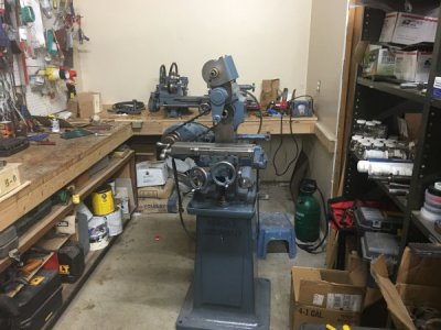
Pics above tell the tale...

Also, experimented with the round threaded "lock nuts" that tension the bolts that hold the vertical gib in place for the Z axis table casting. Still haven't found a similar example on line. But it looks like these are used to lock the tension on the vertical gibb bolts. Seems to work well, if a bit odd.

Also discovered cap screws don't work with this casting as the head of the lowest cap screw binds up against the flare lower part of main base casting, causing the downward movement of the table to get stiff and stop working 2 or 3 inches from the bottom. A regular hex head bolt clears just fine.

All in all, very happy to get this baby ALMOST ready to use!
 
Last edited:
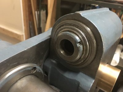
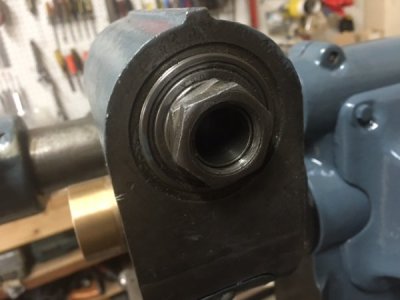
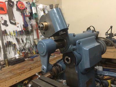
image.jpeg image.jpeg image.jpeg Ok, next issue. Tried to mount the vertical milling attachment this evening. Very hard to aline the arbor with the attachment and what I assume is an existing collet in the assembly won't come out. Maybe it's not a collet, but the actual spindle???

Anybody have an exploded view drawing of the vertical attachment. Iam trying to understand how this things works...

Any suggestions.

Thanks
Glenn
 
Last edited:
Glenn,
The shaft has a keyway in it and the bronze gear inside the head has a key stock,cheek it with a light
the shaft need to go in and engage the the keyway,The bronze gear floats inside so you will have to align the gear with the shaft as you do this.
Also I don't see the shaft for the vertical head in any of the photos,The bronze bushing that is in the last photo is part of the bronze gear assembly
attached a copy of the Vertical head drawing.
Hope I got this right and hope it helps.
Regards
Wally G
dgehricke
 

Attachments

  • Burke #4 Manual Vertical Milling Attachment Assy Parts copy.pdf
    190 KB · Views: 18
That is the end of the spindle. It takes 3C collets. There should be a drawbar to hold the collet in. I made one cause mine was missing. I have a print for making it if you need it.

Seems many of these machines are slightly different. Maybe depending on year made. The center lock nut on the vertical gib on mine has a handle to tighen and lock when milling , which you WILL need to do.

There is a long shaft with a keyway goes through the vertical head and into the spindle of the machine. It lets you move the head in or out for position as needed. I had to make that too. If need, I have a print for it also.
 
Also, on the table you have socket head cap screws for the gib screws. I found it better to use set screws and locknuts. They don't stick out so much and get in the way.the second screw hole in from the left should have a bolt with a handle to lock the table. Mine was missing so I use a SHCS in that spot.

That is a beautiful machine and looks like it is in excellent condition.
 
Last edited by a moderator:
Back
Top