That helps.
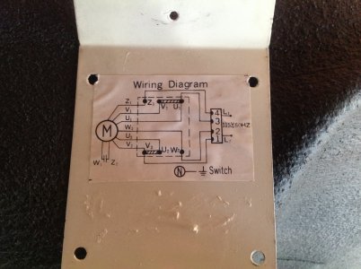
The switch that you removed only had 4 wires to it, correct? The dotted line of your diagram is a terminal board (with V1-U1 connection and V2-U2 connection), and that is mounted elsewhere (maybe inside the junction box on the motor)?
Did you label the wires you disconnected from the switch, or do they have the labels on them (should be Z1, U1, W2, V2)?
I can easily tell you how your motor was hooked up:
Your motor has three sets of windings. Two are RUN windings (V1/V2 and U1/U2) and one is start winding (Z1-W2) with a centrifugal switch (W1-Z2) that turns it off as the motor picks up speed. You have a dual voltage (110 and 220) motor, and depending on which voltage you want it set up at depends on how the two run windings are connected. In your case, it is setup as 110V, which is why V1 and U1 are jumpered together and V2 and U2 are jumpered together.
The old switch always provided the same polarity to 1 &3 when fwd or reverse, and reversed the polarity for 2 & 4 to start the motor spinning in the desired direction.
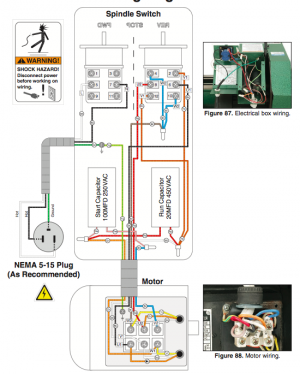
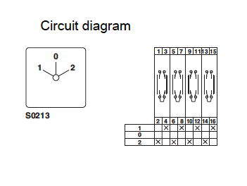
Where I am stumped right now is figuring out the internal schematic for your new switch. The Grizzly manual shows the connection for a capacitor start-capacitor run motor, which you don't have. It is a reversing switch, which means some of the contacts are connected internally (for example, 1-3-5 and 7-9-11). If I had it sitting on the bench in front of me, it would take about 20 sec to figure it out.
Unfortunately, there are quite a few different circuits for these things. Below is one example, but it definitely ISN'T the way your switch is built (The Grizz 9x20 has a jumper from 4 to 10, which means when you reverse the lathe, the switch below would short line and neutral together. Bad news):
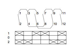
I drew out what should work in the circuit grizzly has on their 9x29, but I am afraid that it is only one of about 6 possible circuits. I personally would not blindly hook up the motor based upon my guesses; I would check the switch with a multimeter first (not hard) to find out which contacts close as the switch is cycled.
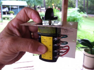
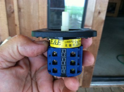
By any chance the grizzly switch didn't come with a diagram, did it? Are there any other part numbers on it besides the LW8PS I can read in your photo? My google-fu is weak, I cannot come up with a circuit diagram for a LW8PS switch.
Got to home depot and buy a multi-tester for $20, and you can learn to use it. It is easy.


