Help me translate caliper to mill measurements

chris.trotter

Registered
Registered
Joined
May 14, 2013
Messages
104
Will do my best to represent what happened, this was last night and I'm going off memory for the specific numbers, but the gist should make things apparent.

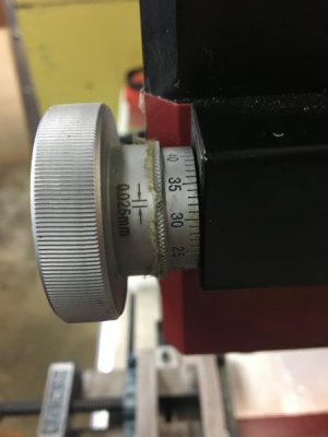
1. My mill's z-axis knob indicates each increment is 0.025mm. (LMS hi-torque equivalent)
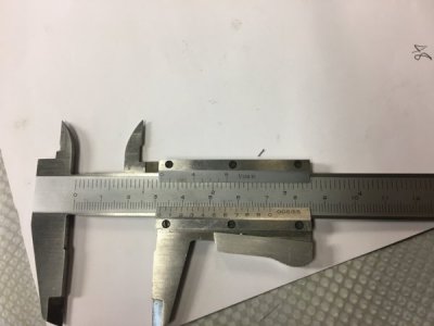
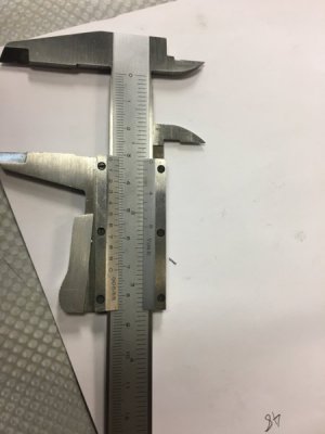
2. My vernier caliper says each increment is 0.05mm. (it is, admittedly, a really cheap caliper)

- I measure 3.225 on the caliper.
- I need to take material off to hit 3.125.
- This is a difference of 0.100.

I get my z-axis 0, then turn the knob 4 increments (4 times 0.025 = 0.100).
When I re-measure the part, it measures 3.200. (i.e. it seems to take off 10% of what I expected it to)

What am I misunderstanding about the z-axis travel increments, and/or my caliper's increments?
2018-03-08 07.23.13.jpg
2018-03-08 07.23.53.jpg

2018-03-08 07.23.53.jpg
 
I can't see the pic of your calipers really well, but I think it's saying that the vernier reads in 0.050mm. The main scale should be 0.100mm I believe. Check some gage pins or other known sized objects and verify you are reading your calipers correctly. I think that's where the problem is.
 
Yeah, pretty sure I'm reading the calipers correctly (read/watched several different sources on how to use vernier calipers), it's identifying what the z-axis dial actually does that is confusing me. For example, the dial goes from 0-59. Why 60 divisions? Why not 50? Or 100? I have a depth gauge, so I can always do a facing cut, then cut a slot at a known depth on the z-axis dial and measure. But that seems kinda silly.

Also just realized that perhaps the LMS manual for the hitorque says something about reading the scales, will check that out.
 
From a review of my mill:
Once engaged, fine feed is obtained by turning the dial clockwise to feed downwards, one complete turn moving the quill down by 1.5mm and there are 60graduations of 0.025mm .

Maybe I just haven't figured out where the backlash ends on the fine feed knob (and there is a LOT of it).
 
At first glance this appeared as an aggressive machining.
But to put it in US specs you have an 1/8 inch .12697 of steel in the vise and your gonna take .004 thousandths .00394 off of it
to arrive at .12303
Using the Z so cutting on the end of the end mill.
I feel your overestimating a milling machines ability. There are many things in play here that can cause these things.
When the end mill hits the work it is going to try and resist and be pushed upward, any machine flex will be taken out and it will
continue the cut to the end where it will fall off towards the end as the upward force becomes less than the cutting force of the last part of the end mill to leave the surface. Even worse with carbide tooling as the cutting resistance is greater.
Then there's always the opposite on deep cuts where the end mill is sucked down into the work and cuts deeper.
Then there's climb milling and conventional and the differences they give as the end mill is pushed or pulled sideways.

Many more things..like vise jaw lift, etc.

It's a learning curve to see what your machine does and adjust to get the results you want.
Trying to hit 3.125 (.12303 in) is over optimistic. That's for surface grinders.

your dials at .25mm are basically english at .00984 in. per line or .001
 
It helps to zoom in on the picture by using your CTRL button and then press the + just to the left of the back space button.

Yes screw infeed screw to eliminate the back lash. You also need to have it that way when taking a cut. If you still have a problem mount a mag base on saddle and put an indicator on the cross slide and use the indicator to learn what's going on. Might help to buy a electronic digital vernier if you have problems reading your old one. Even experienced machinists have issues and employers buy electronic digital calipers so their people cutdown on mistakes.
Several on Ebay like this one: https://www.ebay.com/itm/6-inch-150...529401&hash=item2a6add9f76:g:gZkAAOSw3ydVjuch
 
Bah. Yeah, it auto-resized the pic for me. I've just moved to a new computer (a Mac), so have to re-learn all my old workflows. And yes, the LMS version of this machine is graduated in 0.001" divisions.

Using the indicator to double-check crossed my mind, but I figured "I must just be doing something dumb here". Will try that!

@rgray - for some clarity, with my hogging cutter (I think it's HSS/Cobalt) I can take a 50-division cut. What I was taking in the example was a 2-division cut. As far as accuracy, I'm fine with being inside 0.010mm - reasonably confident I can hit that. My real concern is the cut I thought I was taking was not happening (by a hugely wide margin).
 
When the end mill hits the work it is going to try and resist and be pushed upward, any machine flex will be taken out ...

As rgray said, there are many things that can account for what you're seeing. One of them is what he alluded to above. If you dial in a cut in Z, any backlash in the Z-axis lead screw will be taken up by the cutter before it starts to cut. To see if this is an issue, try lowering the cutter below the amount you intend to cut, then raise the head back up to the right depth. This takes the backlash out of the screw. Then see what the cut produces.
 
My real concern is the cut I thought I was taking was not happening (by a hugely wide margin).

That's all I addressed.
I didn't pay enough attention to the calipers.
In the picture they are on 32mm and the US side is unfriendly....it's in 1/16'ths so it's just over 1 & 1/4 inch by the lines. 32mm=1.25984

So if I had paid attention to the calipers ....you write 3.225 as a measurement . That's centimeters?
Then 3.225cm=1.26969 and minus .1cm=.03937 for end result 3.125cm=1.23031in

Your scale says 005 main scale is in mm lines there are 20 vernier lines so there is supposed to be a decimal 0.05 resolution.
Maybe there is a dot there I can't see.
Or maybe I've completely confused myself...wouldn't be the first time.
 
Ok, that might be what I'm doing wrong. Here is how I've been removing slack from the z-axis.
- Lower quill manually (using handles) until I'm a half-inch or so above the workpiece, then push in to engage fine feed
- Using fine feed, feed quill downwards until cutter is just above workpiece
- Turn power on, set spindle RPMs
- Using fine feed, lower quill/cutter until it just starts touching - my 0 mark
- Look at z-axis division number, jot that down as my "0"
- Move cutter over to the side of the workpiece (so I can lower it without hitting the workpiece)
- Using fine feed, lower quill/cutter using divisions to match expected depth of cut

But it sounds like I need to take the slack up the other way...?

@rgray yeah I've been ignoring the US side of it, just looking at mm.

Also, kinda looking like I need to do some investigation, perhaps because there is z-axis lock, it's pushing back up? Will have to try again and observe more carefully.
 
Back
Top