[Newbie] Help me decipher wiring diagram.

xbartx

Registered
Registered
Joined
Sep 9, 2024
Messages
40
I have a Stepperonline servo and controller that I'm having issues resolving. Biggest issue is most likely my lack of knowledge, but I think there are other factors making it harder. The product looks to be new, the communication with the tech is slow and a bit clumsily being in China. I have pointed out a few flaws in the manual that have been acknowledged and features not documented.

Current problem is that I'm trying to wrap my head around the wiring of the brake, this servo has an internal brake.
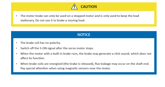
In the manual it states" When brake coils are energized (the brake is released)" It sound like that the brake is always on unless the 24V is applied, does that sound right?
Here is a diagram from the manual, I'm having trouble with the relay and how it is wired. Is a Double pole, single throw relay shown? Why is nothing connected to the relay inputs?
-Brad

Screen Shot 2024-11-17 at 9.44.51 AM.png
 

Attachments

  • Screen Shot 2024-11-17 at 9.45.29 AM.png
    Screen Shot 2024-11-17 at 9.45.29 AM.png
    37.5 KB · Views: 1
I think that the servo drive can't support full brake current, so it needs an external relay.

The relay coil is the small square in line with DO3+ and has a suppression diode.

The diagram shows the connection between the switch contacts and coil as a dashed line. Why the two components of the relay are separate, I have no idea. I hate this style of electrical diagram.
Is the +24V that is shown next to the relay coil and diode the voltage for the relay coil? and not the 24V for the brake?
 
I think it's both. The drive doesn't appear to have an internal 24v source.

Looks like you need to supply an external source for both the relay coil and brake coil.
 
It doesn't. Single pole would work also.
It's possible the factory has got it backwards and the brake is only energized for braking.
It depends on how the mechanism is configured to operate.
 
Last edited:
It doesn't. Single pole would work also.
It's possible the factory has got it backwards and the brake is only energized for braking.
It depends on how the mechanism is configured to operate.

I just test the servo out by applying 24V to the brake and sure enough the brake released.
Sure seems backwards, but what do I know!
 
I just test the servo out by applying 24V to the brake and sure enough the brake released.
Sure seems backwards, but what do I know!
It’s called a deadman brake.
If power is cut off, operation stops.
There are a lot of these type of brakes in my industry
 
Back
Top