Grizzly G0678 8x30: Repair, Scraping and Alignment

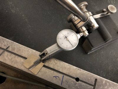
Basically what I did was lay the dowel flat, but sweep using the ball end of the indicator [against the dowel], and look for maximum height.

Ah. I see.

Yes, for a scraped surface you want something to average out the scraped points. I think a gage block or parallel might work better, though, and is more commonly used for the purpose. I'd rather have the ball against a plane than against a cylinder. Any vertical discrepancy will translate to a horizontal discrepancy with the latter. The carbide blade you used at top is probably flat and parallel (but I'd still check it!).

I've tried using the ball at the end of the indicator stand rod to test squareness, but without much success. Rich told me that's indeed it's intended purpose, but it's so small that it's tricky to get an accurate reading. I slotted the front of my indicator base to hold a small plate with a curved front and use that for the purpose (the curve doesn't even need to be terribly accurate — belt sanding or filing a fair curve suffices). That or a large steel ball held in a vee works better for me.

I think you should get your plate re-ground and calibrated if you don't trust it, though. You're almost certainly fooling yourself if you think you've made something more accurate than the plate by scraping it in relative to the plate! If the part hinges well on one part of the plate but differently on another (and you've ensured everything is spotlessly clean) then there is no way to know which area is truly flat (probably neither).
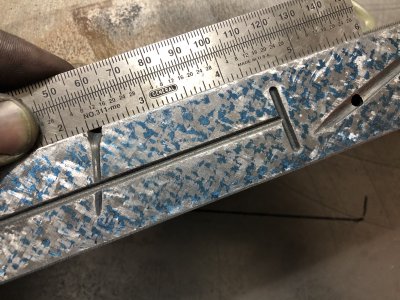

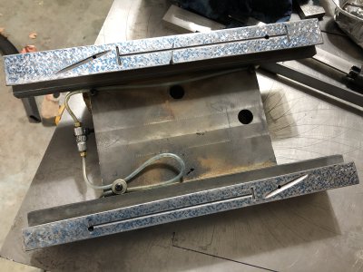
It is a little tricky using the ball end and lining up the indicator so the apex of the ark is close to perpendicular, def takes some time to line them up right.

I did measure the carbide, it’s dead nuts flat. I considered my gauge blocks, but didn’t want to chance scratching up the faces. I used both a dowel and parallel. We’ll see what the metrology lab at work has, the guy that runs it wants to take a look at this square.

I did some basic tests of flatness of my surf plate, used my Starett 199 on a 6” between centers and didn’t record any true dips, and sweeping with my tenths indicator didn’t show any clear patterns of dips. There does seem to be a slight dip in the front middle, from doing the spherometer test, but it seems to be too low to register on a tenths indicator.

My surf plate is a 18x24 black Starrett, and I do wonder what it might cost to get the surf plate lapped. In my experience, at least here in Indiana, shops only want to deal with commercial customers, and quote egregious prices to individuals. Like I tried to get some parts ground, and places I talked to wanted me to set up a commercial account, pay for all sorts of consulting fees and had something like $5,000 minimum order. Might be cheaper to buy a new one from Shars.

Anyways, I don't find it surprising that you can scrape something that's more accurate than the surface plate used as a master if the sampling distribution is uniform. The law of large numbers, in probability and statistics, states that as a sample size grows, its mean gets closer to the average of the whole population. So, when I'm working on improving the pattern, I make sure to sample from different areas of the surface plate, and avoid inking in the same direction / pattern. This way, I sample a larger distribution of the surface plate, and get closer to the mean flatness. Also, when I get to finish scraping, I don't scrape every high spot, instead, I do a random sampling, and only look to improve the statistical distribution of spots. Basically similar idea to when you're painting a car, and doing many light dusting coats.

One of the projects I do want to make is an autocolimator, might make one and lap my plate when I get all this other junk finished. I really do need to get back to making car parts, so I need to get my stupid mill fixed.
 
Last edited:
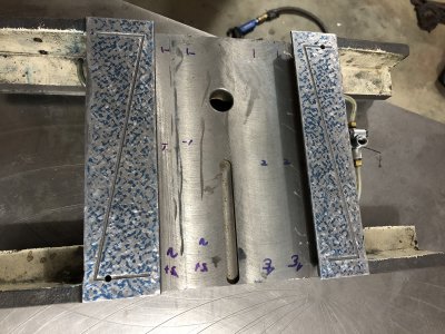
Got some more work done on this. Got both sides of the saddle scraped in, and both sides are parallel to about 2 tenths over 10”.

I know the bottom of the saddle isn’t perfect, there’s a 1/2” spot towards the outside where the ink density is pretty low, but I’m not too bothered about it.

Not sure, but I’m thinking this ink pattern is good enough for mill ways.

In any case, it’s multiple orders of magnitude better than what it was before. Before, both the top and bottom looked like they were cut with an axe, and had like almost 20 thousands dips and way way out of parallel.
Now going to use the saddle as a master to ink the knee.

The weird thing is that this is actually a really nice casting. The iron is very even, no casting voids or bubbles at all, very nice uniform grain structure and scrapes very nicely. It’s definitely a better quality casting than my 1950’s Clausing. It’s just the factory finishing thats horrible.
 

Attachments

  • FB8A3C55-7464-409D-A3C6-918981D759CA.jpeg
    FB8A3C55-7464-409D-A3C6-918981D759CA.jpeg
    3.8 MB · Views: 42
  • 2F7CA705-C4CE-48A2-B57F-A0C5B9A01FA3.jpeg
    2F7CA705-C4CE-48A2-B57F-A0C5B9A01FA3.jpeg
    3.3 MB · Views: 35
  • DABE3020-7163-46AF-84BC-EB14B1C2EB23.jpeg
    DABE3020-7163-46AF-84BC-EB14B1C2EB23.jpeg
    3.2 MB · Views: 35
  • 07D5E6D4-649C-418E-B89E-8B99B5C84233.jpeg
    07D5E6D4-649C-418E-B89E-8B99B5C84233.jpeg
    3.9 MB · Views: 38
  • D18F4925-C83A-48C4-8DEC-780F40333C36.jpeg
    D18F4925-C83A-48C4-8DEC-780F40333C36.jpeg
    2.7 MB · Views: 43
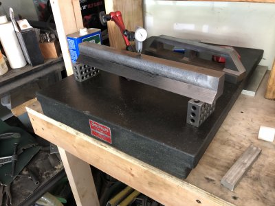
Got the box square scraped in. Been swamped with day job stuff so haven't had a chance to work on this.

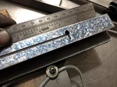
Took the square in to our instrumentation lab at work, and measured it in the clean room, it's flat and parallel to 50 millionths, and square to just under a tenth.

I'd say that's decent for a first time at this.
 

Attachments

  • IMG_5865 2.jpg
    IMG_5865 2.jpg
    352.7 KB · Views: 31
Getting back to this project, been swamped at work for a while.

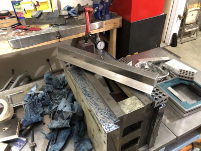
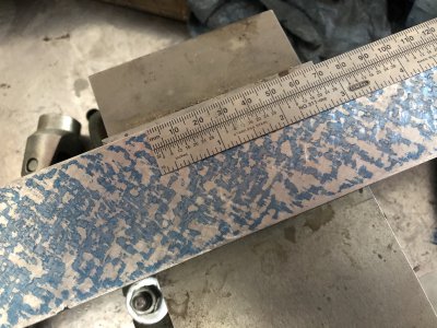
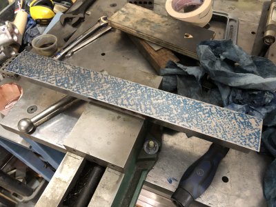
Finally got around to scraping in the ghetto straightedge I made from an old sewer grate, now using it the scrape in and align the knee ways.

Knee ways originally started out with about 15 thousands of twist, now down to a few tenths, still doing a rough scrape on the knee.

Note, the twist wasn’t from wear, that’s how the surface was ground at the factory. I’m guessing the casting must have slipped during the grind operation, or maybe they they had to re-position to grind the left and right ways and didn’t align it properly, don’t know. All I know is it was pretty sorry shape when I started and that clearly explains why I could not mill a square surface.

To ensure the knee top flats are co-planar, I first scraped the saddle in on the surf plate, and I alternate between printing with the saddle and with the straight edge. You need the straightedge to ensure the length of the ways is flat, and the saddle to ensure both flats are co-planar. I also regularly check for twist to make sure nothing is getting wonky.

With the straightedge, when I get around to it, I might scrape a few more PPI in the straight edge, but figure this is good enough for now.
 

Attachments

  • 07A43E97-410E-466D-B558-E88D81961C83.jpeg
    07A43E97-410E-466D-B558-E88D81961C83.jpeg
    3.1 MB · Views: 26
  • 4380909A-3259-4324-9A8E-B2092B668303.jpeg
    4380909A-3259-4324-9A8E-B2092B668303.jpeg
    3.5 MB · Views: 26
  • A0080540-EEB8-43AB-88D4-CC367E3017B3.jpeg
    A0080540-EEB8-43AB-88D4-CC367E3017B3.jpeg
    3.7 MB · Views: 21
  • 58D16034-86F2-4912-A71D-4E1FDC607F44.jpeg
    58D16034-86F2-4912-A71D-4E1FDC607F44.jpeg
    947 KB · Views: 26
  • A96657E9-F58D-496A-8A9C-817D09B08981.jpeg
    A96657E9-F58D-496A-8A9C-817D09B08981.jpeg
    2.6 MB · Views: 28
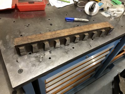
fantastic work, that'll be a cracking mill by the time you're done. Any plans on doing the head/ knuckle junction? I remember reading about someone else scraping in a small knee mill like this and that was another area that benefited from some work. How long did it take you to machine your straight edge to rough shape? Looks like a decent sized lump of CI!
 
fantastic work, that'll be a cracking mill by the time you're done. Any plans on doing the head/ knuckle junction? I remember reading about someone else scraping in a small knee mill like this and that was another area that benefited from some work. How long did it take you to machine your straight edge to rough shape? Looks like a decent sized lump of CI!
Thanks man, it's getting there, very slowly though. Have a day job and don't have a lot of time to work on this.

For the time being, I'm just going to leave the head / knuckle junction alone, I just want to get the mill back together, got a lot of projects I need to get done with it. But I'll definitely re-visit the head/knuckle when I get some time.

I'm planning on making a vertical shaper attachment that would bolt up where the motor currently sits, and re-locate the motor flipped 180 degrees vertically, closer to the head.

That straight edge, I think it took maybe an couple hours with a sawz-all first, then probably 3-4 hours of milling time. This isn't the most rigid mill, so it was limited to about 0.030 depth of cuts with a face mill.
 
How does one know when a piece of metal is fully "relaxed" and not subject to movement as time goes by? If there are stresses in the metal and part of it is removed then the stresses will cause the metal to change shape. I've seen this in cast iron.
 
How does one know when a piece of metal is fully "relaxed" and not subject to movement as time goes by? If there are stresses in the metal and part of it is removed then the stresses will cause the metal to change shape. I've seen this in cast iron.
If you want to get fancy about it, you send it out to get thermally stress relieved. In a home shop, you can shot peen it , or hand peen it with a hammer. That would cause many stressed lattice dislocations that are susceptible to move to move. Or you can leave it outside for a while.

Basically the idea is you want to encourage any movement that will happen, to happen before the final finishing operations.
 
Back
Top