Grizzly 0761

Turbine-Wine

Registered
Registered
Joined
Sep 28, 2022
Messages
39
I am just finishing up building a plasma table and wiring in the electronics. I am now moving on to my Grizz for CNC. It was only now, that after searching the net, that I find no one is converting the 0761. There are tonnes of videos on virtually every other model. none for 0761 I can find? So break it to me gently, is the 0761 not a suitable candidate ?
 
I own a G0761. It's a fine drill and tap machine and is decent for light milling. But PM makes a far superior candidate for CNC conversion the PM940V.

Let's start with PM's 12 inches of travel on Y that's a HUGE advantage for CNC. You put a Kurt vise on the G0761 and you can barely squeeze 6 inches of Y travel out of it. The PM also has a 5,000 rpm spindle which is far more suited to CNC of aluminum vs the barely 2,000 rpm on the G0761.

Want to know what a gear head mill at full throttle sounds like for hours on end doing CNC...WHAAAAAAAAAAAAAHHHHHHHHHHHHHHH AT 90 plus decibels. I'm guessing that PM is a much quieter belt drive.

I have been down this CNC conversion road before with a G0761 type gear head mill. Huge money pit. I would never do it again to infinity but if I did I'd pick something like the PM mill. Obviously another advantage is there's a company making kits to convert them.
 
Now that said, if you are undeterred about converting the G0761 here are a few thoughts. Seriously look into converting it to belt drive and upping the spindle speed. Counterweight the head to take the weight off the Z servo. Convert to some form of variable speed drive. Think about one of the quick change tool systems, swapping R8 tools is slow and annoying in CNC use. Think about an enclosure to contain the coolant and giant chip mess it will fling in all directions at higher RPM's.
 
Now that said, if you are undeterred about converting the G0761 here are a few thoughts. Seriously look into converting it to belt drive and upping the spindle speed. Counterweight the head to take the weight off the Z servo. Convert to some form of variable speed drive. Think about one of the quick change tool systems, swapping R8 tools is slow and annoying in CNC use. Think about an enclosure to contain the coolant and giant chip mess it will fling in all directions at higher RPM's.
Well, the 0761 is my last mill/drill so will try it. Counterweight idea for head makes a lot of sense, that sucker weighs a ton. Have you seen any counterweight designs?
 
Well, the 0761 is my last mill/drill so will try it. Counterweight idea for head makes a lot of sense, that sucker weighs a ton. Have you seen any counterweight designs?
I have recently, it may have been in a youtube video of a PM 940V CNC conversion. The square columns make this fairly simple to go up, over the top and down the back side where weights attach. The one I saw in the video was using chain like bicycle type chain but I have seen them use steel cable and pulleys also.
 
I have recently, it may have been in a youtube video of a PM 940V CNC conversion. The square columns make this fairly simple to go up, over the top and down the back side where weights attach. The one I saw in the video was using chain like bicycle type chain but I have seen them use steel cable and pulleys also.
Thanks, found the video you referred too.
also another on using air shocks, I think I may pursue that one, seems a more linear weight absorption process than a straight weight and possible easier to do. Minute 15 of this video
 
I have no hieght restrictions in my shop so may look at mounting the shocks above the unit without chains, or even to the side. Not really a machinist so not aware at the moment "what would or would not be in the way. Second thing I will look at is to see if there is room in that massive square tower the 0761 has, that the head rides in. So, maybe a single shock. One pushing up....not sure yet what the best approach is. Just seems to me that big chunk of square steel must have a void in it somewhere.
 
Did you note the linear guideways and bearings he was using in the first video? One issue with CNC conversion on these Z dovetail ways is the head will nod forward out of flat with the table if the gibs are not locked, but you can't lock them on a CNC so it's a fine balance of snug but not too snug, some weight from the head, but not too much weight that it strains the stepper or servo motor you are using for Z. Years ago I saw a guy who installed linear guideways on his Z but that was a whole operation and not cheap.

You know...one alternative vs going through all the trouble of converting this mill to CNC is just buy a used CNC bed mill. There was a Trak for $7k near me a couple months back. I gave that serious consideration. You will have that at least into a converted G0761.
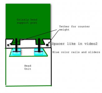
Let me play Devils advocate for a moment.

Plan 1- Using the spindle drop as the Z axis instead of the head may be the easiest to do. I would mount a motor on the opposite side of the Handle that drops the spindle. This gives me 5.5 inches of Z axis "after" placing the head at the best place for the job to be executed and lock it. A good "Home" G Code should tell the spindle when its on the corner of the work, Just as the "head does in a regular Z axis movement.

Plan 2- The squeeze guides that are presently used to slide the head unit are about the length of my Table. Cutting or stacking plate steel to represent the spacer should be relatively easy. 3/16ths steel over the existing pinch rails on the post gives me a flat surface to mount rails. Rails are tapped and drilled into the head support post through the old pinch rails. Lots of meat there.
Now, not sure if the slider portion can be bolted into the gear box.


Plan 1 is cheap cheap cheap.
Plan 2 is not :)


Will have to look into bearing support for spindle and see if I can beef them up.

Comments?
 

Attachments

  • 2024-11-11_190805.jpg
    2024-11-11_190805.jpg
    72.7 KB · Views: 3
Plan 1 is not ideal because an unlocked spindle is way too loose for milling, too much chatter. Many, perhaps most CNC conversions move the spindle to the top and lock it for max rigidity. Maybe apply Turcite to the Z axis ways as a happy middle ground.

Regarding your attachment, having counter weighted one of these before I found a neutral position further out from the column so there was about as much weight forward and rear of the attachment point. Knowing I'd have to leave the gibs somewhat loose I tried to get the weight of the head balanced front to back.
 
Back
Top