About ten days ago I promised a description of an instrument i made.
There was some response.So now i am again on my feet after a bad fall,
i proceed with some pictures and description.First the pictures.
View attachment 94711View attachment 94710View attachment 94713View attachment 94712
Pic 1 Pic2 Pic3 Pic4
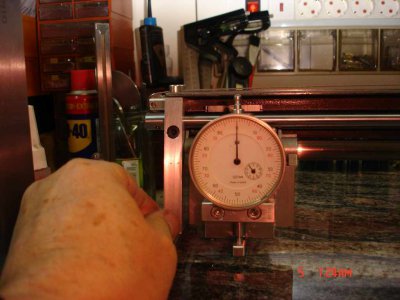
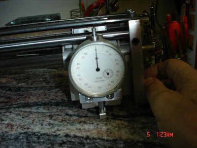
Picture 1 is the slab.It is a piece of Brasilian (i am told) granite.Also picture 2 is
the same slab with a Mahr 1μm comparator dial which was used for the calibra
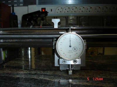
tion, for scaling. Picture 3 is the underside with the 3 adjustable feet for the leveling.
The feet are 3 M10 inserts in 10mm holes drilled with an SD type hammer drill and
glued with Araldite two component epoxy.The 3 points are Airy points so the
flexing of the slab is minimized.Picture 4 is one of the feet.Sorry for bad focus.Macro
function of the camera was forgotten apparently.All pictures are reduced in size.
View attachment 94714 View attachment 94717View attachment 94715View attachment 94716
Pict 5 Pic 6 Pic 7 Pic 8
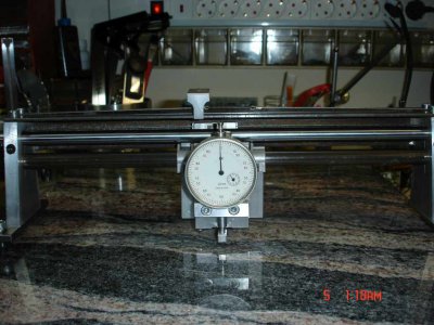
Picture 5 is the instrument.
It consists of Two aluminum trapezoidal sides separated and held by a piece of 25mmx32cm
angle Iron,and 2 round rods from an old printer.The one,12mm diameter, supports the
carriage with the dial indicator and a vertical adjustment slide mechanism.The other,10 mm dia
simply restrains the carriage assembly from rotating.Pic 6 is a side left view.
There is a mechanism consisting of a handle riding on top of the iron angle, a steel string with
tightening spring and 2 rollers for moving the carriage with the least disturbance possible.
See Pic.7 top view.On the top there is a graduated ruler for the position of the carriage.
The total horizontal measuring span of the instrument is 27 cm.
On the bottom of the trapezoidal sides are 2 "ears". The left carries 2 M6 screws and the right
one M6 screw for zeroing the instrument.
Pic 8 is a detail of the carriage.You can see a small arm that carries the sensing polished carbide
(or black diamond probably) directly under the center of the 12mm rod and also an adjusting
knob for the vertical position of the dial indicator,so the instrument can accommodate a range
of dial indicators,a very useful feature.
Pic9 Pic 10 Pic 11 Pic12bad slab
Pic13
The sequence of mesurment is as follows.FIRST (Pic9) we zero left using the M6 screws.
Then we zero right (pic 10) using the single M5 screw. We repeat left and check.Rezero
if needed.The we move the slide by the handle and check deviation on dial indicator noting the
distance of the slide by the graduated ruler on top.Pic 11 shows the indication at the middle of
the slab. There is a sagging of about two microns.I used a 10 micron dial indicator for this de
monstration But the actual calibration was made with an 1μm dial comparator by Mahr and an
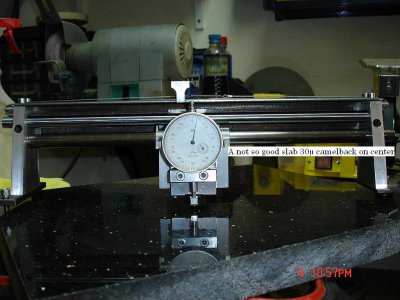
1μm microcator by KRIN Kirov (russian).Pic 12 shows another slab of black granite that is mediocre
with a sag of 30μm at the center.Of course is a matter of luck to find the perfect slab,I was probably
lucky.Pic 13 shows the worst case measurment (diagonal) of my slab.It is about 4μm max.Note
that 1μm is 0.04 tenths!!
There are many tests you can make with the EPIPEDOMETRO.In another thread i will describe how
I verified the straightness of the rods an any other questions that may arise,if i can.
Thank you for subscribing.
Ariscats


