FTV-1 Head Rebuild

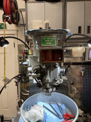
Made some progress this morning, and re-assembled the quill housing. Got the spindle back from C&M on Wednesday. Quick turn around and nice work. Good people to deal with!
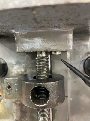
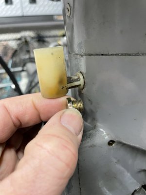
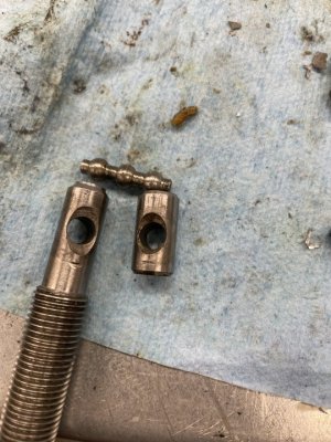
Installing the spindle/quill, cradle assembly( it's on the back side of the spindle rather than the front ala BP ), power down feed, clutch, etc is pretty much the same as a Bridgeport, so I won't bore you with all that. Where it gets different is on the upper trip lever "barbell" area. One side of the upper end of a Lagun micro-screw is dished out/countersunk as is one side of the plunger pin ( see photo ). You install them facing each other.
IMG_9713.JPG
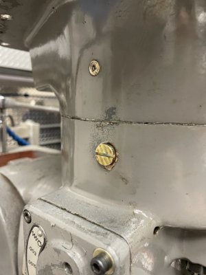
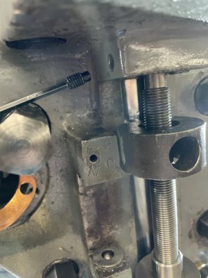
The hole that the barbell goes in is a through hole on a Lagun not a blind hole. The left side is tapped for an adjustable stop screw that allows you to adjust the depth of the barbell. Start out with it threaded in flush.
IMG_9715.JPG
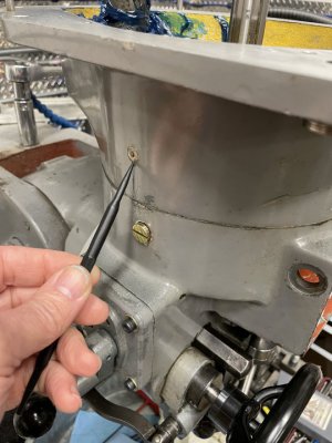
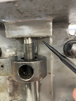
Then install the pivot plunger and the barbell and push up and pull down on the microscrew. The barbell should pivot like a seesaw and you'll see the end of the plunger go from nearly flush with the casting to about 2mm proud. Once it's settled into its place, screw the stop screw in gently until you feel it contact the left end of the barbell, and then back it off a 1/4 turn or so, and install the plug screw on the right.
IMG_9716.JPG
IMG_9717.JPG
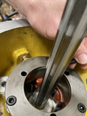
Adjustment of the kick out is the same as a BP. Once everything is adjusted and lubed, it's time to attach the bull gear housing.
 
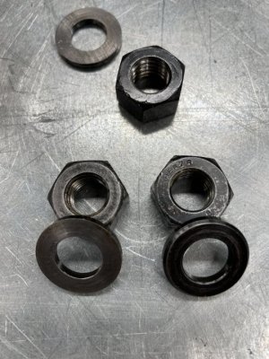
When cleaning the bull gear housing, be sure that the ball oiler port is clear and flows oil, and if you're using the oil cup to lube the spindle, see that it's routed properly. I went with a sealed bearing spindle, so the oil cup will be removed and plugged. Seat the bull gear housing on the quill casting, and just snug up the nuts. They'll get final torqued after the head is fully assembled and run in for a bit, so the moving parts can settle into place. Be mindful of the washer and nut orientation. Note that one side of the washer is flat ground from edge to edge, and one side has a small bevel on the outer edge. The flat side faces up, against the casting, bevel towards the nut. The nuts have markings stamped on one side. Good practice on nuts, is to have the marked side facing out so it can be read as installed.
IMG_9719.JPG
This will be about as far as I can go until a few more parts show up. Namely 6004 bearings for the small bull gear/pinion and the lifter springs for the large bull gear assembly.
IMG_9720.JPG
 
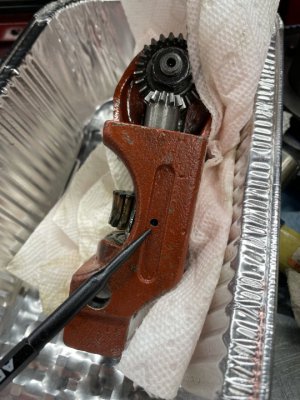
Forgot to add this photo. When you clean/inspect the cradle assembly, be sure this hole is clear, is it's how oil gets to the gear below it. When you pump oil into the ball oiler on the left side ( the one above the oil cup ) it hits the sleeve of the large bull gear housing, and swirls around it and flows down on the cradle, along with dripping down around the outside of the quill.
IMG_9699.JPG
 
FYI, if you have a need to remove the spindle oil cup and plug it, it's tapped for M10x1.0mm. I used an M10 plug screw.
IMG_9722.JPG
IMG_9723.JPG
 
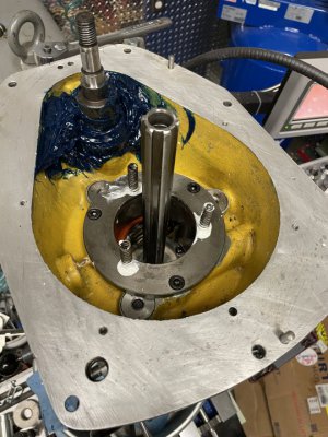
Finally received the remainder of the needed parts, and resumed reassembly. Before installing the large bull gear assembly, insure that the grease zerk for the small bull gear is clear and functional, and also do a functional check on the ball oiler port on the left side. Give it a pump or two, while watching for it to flow freely out the hole on the inside of the spigot/sleeve that receives the bull gear assembly. I also packed the small bull gear area with grease, and in hindsight, would have probably done it after assembly, as it make a hell of a mess, and gets on everything.

Oil goes in here...
IMG_9765.JPG

....and comes out here.
IMG_9766.JPG

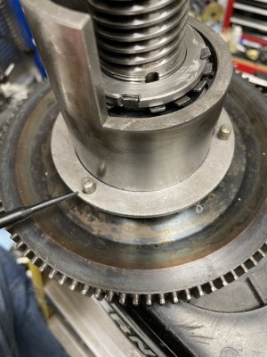
Next is another step I would have done differently in hindsight. The lifter springs for the bull gear assembly. I lubed them with white lithium grease and put them in the holes. I then had to reach under the bull gear with a scribe to make sure they seated on the stubs on the underside of the flange. I think it would have been easier to "glue" the springs to the studs with heavy grease, and then guide them into the holes. Either way, it is critical that the tops of the springs receive those studs.
IMG_9767.JPG
The tops of the springs go over and are located by these studs.
IMG_9768.JPG
 
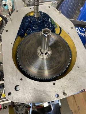
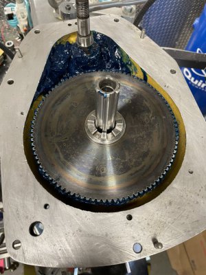
Once the large bull gear assembly is slipped over the spindle shaft, lined up, and lowered into place, push it down against the springs to check for any binding, interference, etc.. Now its time to install the High/Low shift lever and shaft. Lock the shift lever in Low position, and press down on the large bull gear until it's teeth mesh properly with the small gear teeth. Then slide the shifter assembly in until it seats all the way in. You may have to both wiggle it a bit, as well as adjust the height of the large bull gear until the splines mesh. Just be sure you still have good engagement of the gear teeth. Then install the two screws in the shift lever plate. Now you can shift back and forth between High and Low, to be sure everything feels smooth and positive. Also give the spindle a few spins, and transfer some grease from the small gear to the large gear.

In the Low position.
IMG_9769.JPG
And High range.
IMG_9770.JPG
 
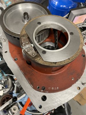
Next is the casting that acts as the cover for the bull gear housing, the bearing support for the lower end of the fixed side of the front sheave, and the brake mount. Lower the quill all the way down, and put the large timing belt pulley( with the timing belt on it ) in it's place on the casting. Now carefully lower the casting down into place, with the shaft of the small gear( be sure the key is in place! ) passing up through the bearing, and at the same time put the timing belt pulley on it, noting key location. "Walk" the assembly into place as far as you can, and then use the mounting screws to carefully, and evenly, seat the casting on to the dowel pins, and tighten into place. Now you can install the brake shoe, and the plate that holds it in place. Place the collar/ring on top of the bearing that supports the lower sheave shaft. Move the shift lever to the High position, to be sure the "castle" on the top of the bull gear smoothly enters the bearing.
IMG_9771.JPG
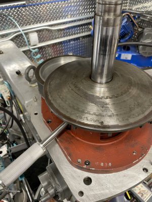
Now put the lower/fixed sheave into place, insuring that the belt teeth fall into place on the small pulley, the "castle" enters the bearing, and the brake drum seats onto the brake shoe. Raise the quill to be sure the shaft passes up through the sheave smoothly, and give the spindle a spin test. Also a good time to temporarily install the brake lever, and test the brake. Take advantage of the brake to torque the nut that secures the timing belt spindle.
IMG_9772.JPG
 
Well, this will be the end of the line for this thread, as I won't be installing the Reeves variable pulleys. Instead, I'm going with a Servo VFD conversion. It would probably be better to cover it in a separate thread in a more general category, rather than the Lagun section, as it gets very little traffic. The Servo system can be installed in just about any Bridgeport type mill.
 
Last edited by a moderator:
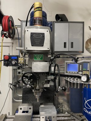
The Servo VFD conversion is complete, and initial test cuts indicate that all went well with the head rebuild. Two thumbs up for C&M Precision Spindle. They did a great job on their "5-Pack" bearing install, and R8 taper grind. A tenths indicator mid way up the taper just causes the needle to quiver, and with a 1/2" end mill in a collet the runout on the end mill is a tenth and a half. Mill runs extremely smooth and quiet, and gives a very nice surface finish.

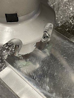
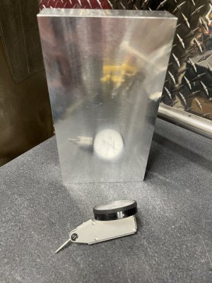
Trued up a 6.50"x3.5"x1.0" block of 6061, and it was flat/paralell to three and a half tenths, with a mirror finish. Using a 4"/ 7 cutter face mill, took a .100" cut at 500 rpm to see if the low end power was up to snuff, and it didn't have a hint of bogging down; surface finish was very good. After that, turned it up to 1000 rpm, and the surface improved noticeably. Extremely pleased at the results, and happy to have the mill back in service.

IMG_9857.JPG
IMG_9871.JPG
IMG_9872.JPG
 
Back
Top