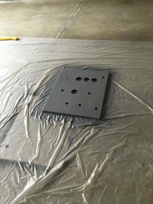
[Newbie] First Cnc Build : Hd Router/mill

Iceman

Registered
Registered
Joined
Apr 17, 2016
Messages
76
I have never built a CNC machine, and it has been years (10+) since I have played around with one. I'm 30, and I am a Flight Engineer / Pilot (not an EE, I don't do industrial automation for work, etc.).

I grew up around airplanes, and I may have a few engineering courses under my belt. The machine is in the drafting phase, and the electronics (the heart) are starting to come together.

System voltage input: 240VAC split phase
Control/Safety Voltage: 120VAC, 24VDC
Motion Control Voltage: 5VDC
Stepper Voltage: 65VDC

Motion Control: Hicon Integra 6-axis motion controller
Stepper Drivers x4: Kelling KL8056
Currently planning Nema23 425oz-in 8 wire Steppers (on hand) - not 100% sure this will be sufficient for all axis.

Safety: Dold Safety Relay (controls main contactor)
-E-stop
-Start/Stop switches

The Teaser:14012885_10153648073736237_176500348_o.jpg
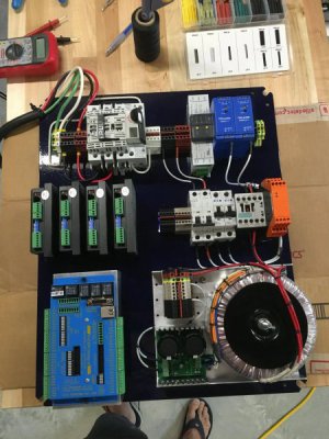
(Shop Approved footwear?)
 
Last edited:
Looking good! Keep us posted on your progress.

Tom S.
 
Very Nice! Looking forward to seeing updates on your build.
 
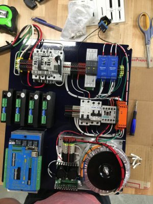
Thanks guys! I've started to partially power and test subsystems - I have yet to power that massive toroid up. I Finally have my comically overkill 100watt 200ohm resister to bleed the capacitors on shut down. I've also decided to add a suppression diode on the contractor coil. I will shortly be posting better pictures, and my schematic that I'm currently working off of (and on - it's very much a living hand drafted document). I will do my best to document this so that it may help others who decide to go this route. There are a few beautiful looking Home built CNC control panels out there, and the details and schematics are scarce, and often lacking in explanation. With everything going on - this project will be 2 years from start to finish. Hopefully I'll be able to capture that. Most likely there will be a youtube video with source documents at the end.

The disconnect I used was for a 3 phase system, so there is an unused leg. I've got 25A fuses in the disconnect which is being fed from a 30A breaker in the panel dedicated for this (10-4 wire). From the disconnect the power goes to a siemens isolator switch that will be mounted on the front of the panel - I could have probably located the parts to remote the main disconnect but that thing is a pain to actuate (probably a good thing) and the isolator switch feels like it was designed for a lifetime of continual abuse in hazardous locations.

After turning on the isolator switch, the next switch which will need to be actuated is the DC Safety and Control switch - a 120VAC switch that provides single phase AC through two MCB's properly sized for two switch mode power supplies - a 5VDC and a 24VDC. The 5VDC is the main power for the Hicon Integra, and the 24VDC is what I chose for control voltage as well as the voltage that will be used for sensors and other such things the system will need.

Controversial topic: the "bonding" of the neg(-) outputs of two different switch mode power supplies. At this point I have decided to the leave the outputs of both power supplies floating (not tied to ground), but tied together so that I only need a single Neg bus (really a 0VDC bus). It is too early to know if this is really an issue. I see for many applications that the negative output of a switch mode PSU is bonded to ground in control applications but not instrumentation (I think due to noise / ground loops).

Like I said - I've taken many classes, but not a PE/EE so, I know just enough to be safely dangerous. Electronics and electrical systems and engineering/machining has been a life long hobby, so sometimes I learn on the spot.

-IM
 
I Finally have my comically overkill 100watt 200ohm resister to bleed the capacitors on shut down.

A 10K, 2 Watt would be more than adequate. ;) But yours will work fine. If you look on the board, there are two bleeder resistors installed. Lower right corner of the board in the picture.

I always bond the - of power supplies to ground. Bring all of the grounds and shields back to a single point. Normally to a ground bus on the main panel. Only connect the shields on one end.

Nice looking panel. :encourage: Looking forward to watching your build.
 
Jim,

There are indeed resisters on output of the 65VDC power supply, my lack of experience had me feeling like these were too small - although I do have a tendency to overcompensate for my lack of practical experience by applying excessive overkill. The golden anodized heatsinks on the 100watt wire wound resisters were too good looking to pass up.

I'm curious to see if any noise is added to the power (and if it even really matters) in this case if I tie all the - to ground (see what I did there?). For some reason there is much controversy over which way is correct (or if indeed it is purely situationally dependent - is there a code that spells out which is correct? I will mess around with the O scope, I already want to witness first hand (because theory isn't enough, trust but verify) the suppression diode reducing the voltage spike from the collapsing magnetic field when the contactor is turned off. Come to think of it - that massive toroid is a fairly large inductor - do people do something similar with suppression/flywheel diodes on power supplies like this to reduce the voltage spike created (on the supply side) when powering down?

-IM
 
The golden anodized heatsinks on the 100watt wire wound resisters were too good looking to pass up.

They are purdy ;)

When mixing power and control signals, I have found it better and less chance of noise if everything is referenced to ground. There is no code that I'm aware of.

It is common to put suppression diodes across relay coils, especially when switching them with transistor logic circuits. It would be uncommon to put a surge suppressor across the primary of the toroid, but you could put a MOV across it. https://en.wikipedia.org/wiki/Surge_protector#Metal_oxide_varistor_.28MOV.29
 
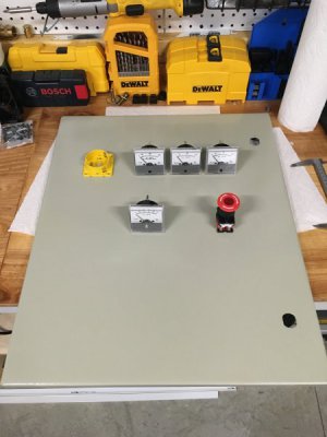
Iceman, you look like you are making good progress since your first set of pictures. I'm a sucker for instrumentation so I like seeing the panel meters. Are these going to measure current to the steppers of each axis?
 
Back
Top