Finding top edge

I've been thinking about making something like this. It also could be used as an edge finder, perhaps handy if you don't want to remove your cutter. You'd want the work surface and cutter to be free of swarf so you're finding the actual work surface.

The circuit is pretty old-school, but the IC still is available -- Jameco has them for $.49 apiece. Any quad opamp that works with a 9V supply and has low offset should work. By "low offset" I mean 2 millivolts or less. Many modern opamps go down into the microvolt range so that requirement is not particularly demanding by current standards. However, the circuit does depend on the "long" leg of the circuit formed by the path from the cutter, through the spindle and down to the body, to be at least 2 ohms. Going with a better opamp may be necessary if the path for a particular machine is less than that.

The device uses super-magnets attached to spade connectors so you can experiment with different locations on your machine to see what works best.
 
I’ve been using ZigZag papers for the last 55 years, bring tool down and touch, if paper can be pulled out without cutting that’s about 1 thou ! Hasen’t failed me all these years, he he he !
 
With the mill spindle stopped move the part in X or Y while bringing the quill down. When you see a scratch on the part you are there.
Same process you would use on the lathe to "touch off"
 
The Z axis movement of my hobby mill ( EMCO FB2 ) is too erratic for the scratching or paper methods to be used. When the Z-axis wheel is turned, the head comes down in a rather jerky manner. Unlike the X and Y axes for which I can change the position smoothly in steps of 0.005 mm ( resolution of the DRO ), the Z-axis position jumps in steps every now and then, sometimes by as much as 0.05 mm. Then I found the Z-axis tool setter mentioned in the replies above and it has become one of my most-used measurement device ever since.
 

Attachments

  • IMG_6213.jpg
    IMG_6213.jpg
    1.2 MB · Views: 32
Last edited:
You also can buy an electronic touch detector -- like this from Shars. It costs more than their Z setter, but it should be relatively easy to make one. Not necessary to make it exactly (say) 2 inches high -- make one and measure its height, from there you're good. A transistor in there would make the device even more sensitive and (hopefully) more accurate.

I have one a bit like the Shars version mentioned here but the top plate is aluminum (I clearly didn't read the product description very well). I don't use it much because I don't think it will hold up, too soft and flexible. But it should be possible to replace the top plate with something harder. Or maybe just put a hardened gage block on top of it. The latter approach depends on having no junk underneath the gage block, as well as a very smooth top surface on the touch detector itself.

The viability of these options really depends on your particular needs. Getting below .001" accuracy likely is going to be more challenging to your wallet.
 
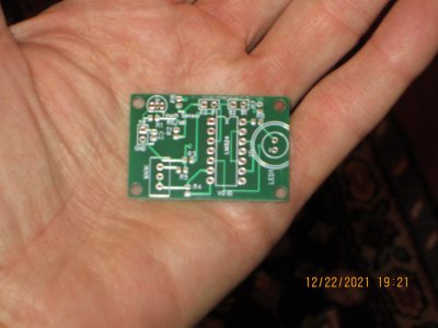
I designed a PCB to implement the touch sensor I mentioned earlier in this thread, but I added the option of using a 4-terminal sensing connection that isn't sensitive to the resistance of the connector wires. It's called a Kelvin connection, see here. I emailed the original designer, Rick Sparber, and he is OK with me making my PCB design open source, so I will do that once I have made sure the board works. BTW, he has since come out with a couple more versions, both quite different from the one I laid out. They also use a 4-wire sensing method, so I didn't really break any new ground there :).

Here's a photo of my board. It's hard to judge the scale of a board when you're laying it out, so a photo of the real thing is helpful. The resistors/capacitors are 603's, about the smallest I want to use for hand-soldering. It should fit just fine in an Altoids-sized box.

touch sensor.JPG
 
Along with the touch-and scratch method, the paper method, there is also the sharpie-and-run-it-backwards method.

None of these is closer than 1 and a ½ thou.
 
I have a battery powered edge finder that seem to work well on the top. It does take some jiggling to eliminate free play (backlash). Keith on Facebook's Vintage Machinery even measures the thickness of the paper and incorporates that in his calculations. He has a DRO.
Have a good day
Ray
 
I designed a PCB to implement the touch sensor I mentioned earlier in this thread, but I added the option of using a 4-terminal sensing connection that isn't sensitive to the resistance of the connector wires. It's called a Kelvin connection, see here. I emailed the original designer, Rick Sparber, and he is OK with me making my PCB design open source, so I will do that once I have made sure the board works. BTW, he has since come out with a couple more versions, both quite different from the one I laid out. They also use a 4-wire sensing method, so I didn't really break any new ground there :).

Here's a photo of my board. It's hard to judge the scale of a board when you're laying it out, so a photo of the real thing is helpful. The resistors/capacitors are 603's, about the smallest I want to use for hand-soldering. It should fit just fine in an Altoids-sized box.

View attachment 389490

I finally got around to building up my touch sensor board and testing it. It works pretty good -- the indicator switches from a no-touch to a touchdown condition without any measureable change in my Z axis DRO. I'm not crazy about the bi-color LED I got though, because the green LED is pretty dim compared to the red. I should have paid more attention to the light output specs for the two colors, but that's a minor quibble.

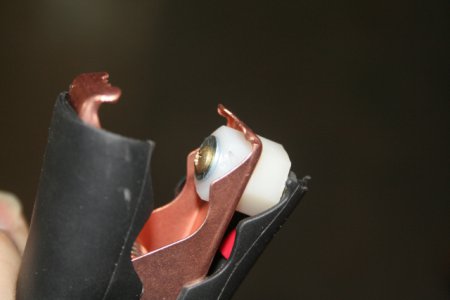
To make the force/sense electrical connections I modified a pair of miniiature battery-charger clips. The original connector wires are used as the force lines. To make the sense contacts I drilled a hole in one of the clip jaws and installed a nylon screw+nut I had modified by drilling/threading a hole down the center, then running a brass screw into the hole. The head makes contact to the cutter or work (through the vise), and the sense wire is connected to the other end of the screw with a spade and nut. Like this:

Touch force-sense.JPG

I learned from the original designer that it's best to have a separate contact for the sense line, rather than just soldering the sense wire to the clip. So that's why I used the modified nylon screws. I placed the mounting hole so that the nut, which is on the inside, is prevented from turning by the bent end of the clip.

I do need to clean up the wiring setup for this -- I used four separate wires and they really get in the way. I think I will get some 4-conductor wire to tame that problem. Or maybe use some spiral cable-management stuff.....I have some (somewhere).
 
I tried today using my 30+ year old and cheap multimeter as a touch sensor for my Emco FB2 bench mill and much to my surprise, the precision is VERY good !

With one probe touching the table and the other touching the arbor, the resistance measured is 1.1 ohm when the tool is not in contact with the workpiece. This value varies a lot depending on the angular position of the spindle. It can go up to something close to 10 ohms but it never went below 1 ohm. As soon as the tool comes into contact with the workpiece, the reading would drop sharply to zero.

To test the precision, I made a shallow cut on the top of an aluminium block with the end of the mill ( 8 mm carbide ) to get a clean datum surface. Then I raised the head, connected the multimeter and very slowly lower the mill head until a sharp drop in reading occurred. Then I locked the head, painted the workpiece surface with a marker pen and did another pass. The paint was not scratched a bit. After that I lowered the head by just 0.005 mm ( or 2 tenths of a thou ) and cut again, the paint was completely removed. This proves that cutter was brought back to the original Z position with practically zero error.

I will definitely use this method a lot more in the future.
 

Attachments

  • 相片 6-9-22 19 04 16.jpg
    相片 6-9-22 19 04 16.jpg
    436.7 KB · Views: 12
  • 相片 6-9-22 19 04 32.jpg
    相片 6-9-22 19 04 32.jpg
    437 KB · Views: 13
  • 相片 6-9-22 19 05 52.jpg
    相片 6-9-22 19 05 52.jpg
    439.1 KB · Views: 12
Last edited:
Back
Top