[Lathe] Fanuc OT to DC_CNC conversion

Galil is simply the gold standard for controlling a servo motor. The card is actually a real time computer dedicated to position control. the little details that make them better number into the thousands. This little trick than Jim just used to redefine the operation of a limit switch is just one tiny example. A major example would be electronic gearing. An axis can be slaved to the operation of another axis. Allows things like rigid tapping, gear hobbing. Another major example would be dual encoders on one axis; allows one on the servo and another on the axis itself, like a scale. Makes super accurate movement possible. So MANY more.
 
Jim, spent some more time with your program...

My Galil Command reference has NOTHING about LD. I assume its stands for LIMIT DISABLE. That's the key I was missing, my program would jump to #limswitch <default limit switch routine> and not always jump back

Does not have HV command either for that matter. I do remember a work around here as my home routine creeps to the index mark.

So I've not been using a full deck. Do I just need to look for a newer command reference? I use all DMC18x0 cards if that matters.

I did a little research and it seems that the 18x0 cards don't have the LD and HV commands available, at least according to my Rev 1.0s manual. Apparently these are a new feature in the later controllers (18x6, 4xxx).

Speaking of new features, I found a ''feature'' in my lathe project. The automatic oiler has a float switch to monitor the oil level so I wired that back to an input to trigger a warning message on the screen to signify a low lube level. So far, so good. I have been running the lathe quite a bit so the oiler has been working fine and finally is low on oil.

Well, it worked better than I could have hoped. :cautious: The float switch contacts closed as they should have, sending 24 volts to the input terminal and simultaneously directly to ground.:eek:. This actually worked out pretty well, it immediately blew the 24 volt control power fuse, and completely shut the machine down, thus preventing it from running without oil. :grin:. That was a bit of an extreme safety feature.o_O

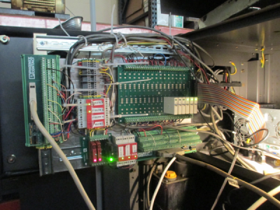
Turns out that the input was being shorted to ground by the shield on the input cable running behind the I/O board. A piece of Nomex insulation slipped between the board terminals and the cable shield fixed the problem. Note to self: Insulate exposed cable shields with heat shrink. :rolleyes:

The board is the one with the white input modules on the right, the board stands off the back panel by about an inch so I ran the cables behind it to save some space. This pic is early in the build, there are a lot more cables running to this panel now but I don't have any current pictures.
1526134926419.png
 
In this case, there are 2 switches and 3 cams on each axis. One switch is the travel limit the other is the home switch. The travel limit is operated by a cam at each end of the travel, the home switch has a seperate cam. Some machines have 3 switches according to a schematic that I have.

Was there no proximity sensor on the machine originally? (if that's even the correct terminology)
Was thinking the mori seiki had that and then roller switches.
When homing it moves full speed till it crosses the proximity sensor, then moves slowly to final home position.

Then there are those unfortunate times that it is sitting to close or past the sensor and I move to home and it moves at full speed to end of travel sets the alarm and will not move no how no way.
Always my fault moving the wrong direction first, happens so fast. Then out comes the 17mm socket and I have to move the axis manually to a safe spot where the alarm will clear so I can home it again.

Getting better about not doing this. With the 2 axises sometimes it nothing more than looking at one and moving the jog handle to make it move when the other axis was the one live and therefore intended movement is backwards.

So no cartesian coordinate system with this new controller? (If that's even a legit question)
 
Was there no proximity sensor on the machine originally? (if that's even the correct terminology)

This machine came equipped with limit switches rather than prox sensors for the travel and home limits. Prox sensors or limit switches can serve the same function, and if I were building a new machine today I would probably use prox sensors. Interestly on the turret positioning there are prox sensors that look to be factory installed

Then there are those unfortunate times that it is sitting to close or past the sensor and I move to home and it moves at full speed to end of travel sets the alarm and will not move no how no way. Always my fault moving the wrong direction first, happens so fast. Then out comes the 17mm socket and I have to move the axis manually to a safe spot where the alarm will clear so I can home it again.

I was having the same problem until I implemented the code above, it doesn't overtravel any longer. I did write some code to allow a limit disable function to allow a jog off of a travel limit. There is absolutely no way to get to the lead screws on this machine to turn them with a wrench. Without removing sheet metal, the only way to manually move an axis is to power completely down and use a 2x4 as a pry bar.

So no cartesian coordinate system with this new controller? (If that's even a legit question)

There are actually two coordinate systems, the machine absolute coordinate system (MCS), and the work coordinate system (WCS). The DRO displays the tool positions in terms of the WCS so that the G Code and DRO agree with each other. Under the covers, the machine is actually working off of the MCS. There is a seperate small DRO display for the MCS.

The MCS coordinates are based off of the home positions (0, 0). All of the tool X, Z positions are an offset from the MCS, since they are in fixed locations, and don't change unless you physically change tools. Each tool is set with the tool setter that is a known point in space based off of the MCS. This is all done with the MPG and a mouse click. In the MCS, all moves towards the work are -X and -Z, so from that perspective you are working in the lower left quadrant of the cartesian coordinate system.

The WCS is an arbitrary point in space chosen during the work setup and is relative to each tool offset, normally the spindle centerline would be the ''0'' of the X WCS. The Z WCS ''0'' is chosen to provide tool clearance from the chuck, so this would be the work length plus 0.5'' or so, and can be on either end of the part, and is normally set with the parting tool since that is normally the operation that is closest to the chuck. So in the WCS you you could be working in any quadrant of the cartesian coordinate system.

From an operator perspective, this is easier in practice than the description sounds, you only have to move one tool into position and one mouse click sets the WCS. Then the WCS is automatically applied to all of the tools. The program math is simple, just addition and subtraction.
 
Last edited:
IT'S ALIVE ! :dancing banana:

Made the first chips today. Finally got it to the point I felt I could test it with real metal in the spindle. Been making piles of air chips. It has been a long journey to get to this point, but it works. A few posts back I said I would have it done Wednesday, well today is Wednesday :grin:

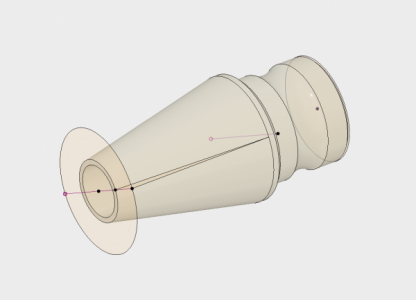
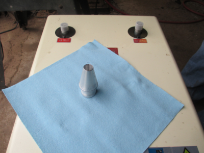
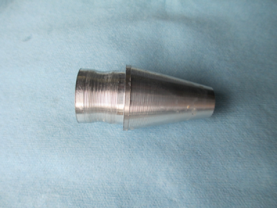
This is what the part is supposed to look like. No point in starting with anything really simple, this is a real world test cut. I have about 400 of these to make.
1526521757686.png


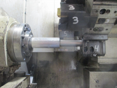
So we start out with 1.5 inch aluminum bar stock. You feed the stock to the stop (tool #4)

1526520755524.png

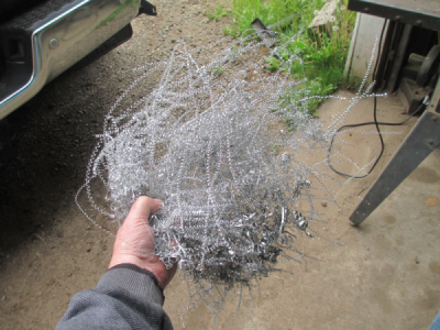
Then create a large pile of chips.
1526520900012.png

And out comes the part. (sitting on top of my new Harbor Freight refrigerated air dryer, need to get that installed)

1526520983791.png

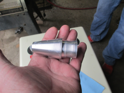
A little closer view. None of the tool settings are quite right, and the feeds & speeds are totally wrong, but it kinda looks like the drawing. :) I have made another half dozen pieces since I took these pictures, and the parts are getting better. I'm learning how to use the machine. Never actually ran a CNC lathe before, it's a lot different than running a mill.
1526521162096.png

And another view give some size perspective.
1526521239064.png

And finally the promised video, such as it is. Sorry for the crappy video production. But unfortunately I didn't want to destroy tools so I had the coolant running, and thus had to have the door closed. I'll figure out some better lighting and a way to video the operation later.

 
Looking good!!! You'll get the feeds and speeds just takes some time.
I tried video with coolant off. Thought I'd just spray wd-40 and make a video. Well it smokes the wd-40 so bad the visibility is almost worse.
I do have a go-pro in the cabinet so one less window to see through.
Here's a link to that vid. I didn't program out the coolant I just hit the coolant off switch every time it came on.
 
congratulations Jim. I am sure you are happy to finally be making widgets.
 
Got the tool settings corrected, and adjust the feeds and speeds to more correct values. I thought I was going nuts, I couldn't get the sizes to come out right. Turns out the G code was wrong and was making the back diameter 0.010 oversize. :mad: To compound the problem, the tool that I was using as the master to set the rest of the tools, thinking that it was correct, was the one not cutting the right diameter. Turned out I was chasing my tail. Normally I would not use a master tool, but I was trying to calibrate the tool setter position and needed something to calibrate to.

I finally figured it out when I set 3 the tools to the spindle centerline rather than the tool setter and checked the cuts on each tool. In that test they cut within 0.0002 of each other. So when I cut another part and found the 1.250 diameter was actually 1.260 diameter, but the rest of the diameters were correct, the only possibility left was the G code. So search through the G code and found what should have been a G1 X1.250 move was actually a G1 X1.260 move. o_O The lathe was doing exactly what it was told to do. Why the CAM software is giving me the extra 0.010 on that diameter still escapes me, and thus far I have not been able to get Fusion to cooperate. I edited the G code manually to the correct value and now it cuts correctly :)

Overall not too bad considering all new controls and software, and the fact that I have zero experience on CNC lathes and am learning Fusion 360 at the same time.

I also found out that the lathe will reduce the diameter by 3/4 inch in one pass and not complain about it one bit. I forgot to reload the G code after I reset all of the tools and made a rather heavy cut by mistake. :cautious: Didn't even slow down the spindle, you can remove a lot of metal with a 10HP spindle. :eek:

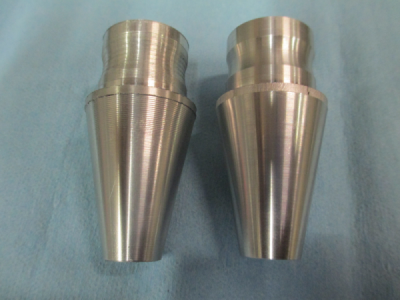
The first part from yesterday is on the left, the last part out is on the right. Getting closer, still need to get the G code to clean up that narrow band on the large OD and chamfer the edges. But other than that, the part is correct to +/- 0.0002
1526609509874.png

Ready to go into production. I have about 1000 lbs of 1.5 inch 6061 round bar sitting on the floor waiting to be converted into these parts.

The next part going to be even more fun, 1 inch x 5 TPI internal Acme thread, 1.25 deep. Thank God for live tools and thread mills, single pointing that one would be a bit tricky.

Stay tuned............... :)
 
Last edited:
Back
Top