Familiar with Pantograph?

Your pantograph ratio is the distance stationary mount to stylus as the distance of the stylus to the pencil. It is the hypotenuse of the triangle that determines to ratio. The hypotenuse being the line from the pencil through the stylus to the stationary mount.

Thanks Doug, that's what I was looking for
 
Here are some links I've saved in the 'future projects' file. PDF plans are downloadable.
http://imageevent.com/tomgriffin/pantograph
http://bbs.homeshopmachinist.net/threads/46469-Get-a-grip-with-a-3D-pantograph!?highlight=pantograph

Coincidentally I am looking at some Ebay spindle motors in the 600watt 12,000 rpm class with included power supply / variable speed control & ER integrated collet. Shallow, light engraving you could probably get away with less power.

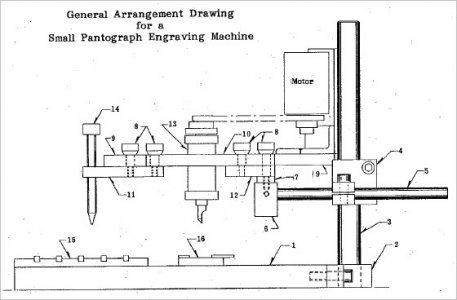
Excellent links petertha, thanks

Good idea the 600W spindle with motor. I have a Dremel tool I got years ago from Canadian Tire as a set including many attachments. Among the attachments there is a flex shaft about 16” long which I never used but it will be quite handy for the pantograph because I can only attach the end of this shaft to the pantograph which is very small and light. For small engraving will be ideal but anything more complicated may not do the job.

I made a pantograph out of paper first to get the idea and next step is to do it in 1/16” pressboard. The final will be with 1”x2” lumber but the links you sent may change my mind and do it in aluminum. Much appreciated
 
No problem. I've made some similar pantograph like contraptions for hotwire foam cutting many moons ago when I had less for machining resources. On those I used 1.25 x 1.25 square section aluminum tubing 0.125" w.t. The swivel joints were pressed in nylon or bronze bushings and ground shaft pins. Nice snug fits with smooth action & all pretty inexpensive stuff really. The stiffness comes from the frame cross section depth, it may not necessarily have to be solid bar. Now this was a pretty low load setup so supporting a motor & possible vibration brings up new considerations. Mocking things up with wood or whatever you can quickly flush out ideas & problems is a good thing IMO.

An interesting concept is adding rotational component - tables or platens between model & pattern. Its kind of 2.5D that can yield 3D-ish copying or scaling. The mechanism gets a bit more complicated because the stylus/cutter also has to be scaled & move according to the same scaling geometry mentioned above.

Thanks for the info petertha

I was searching for a simple inexpensive jig to make simple engraving for tags etc. and I came up a few days back with the pantograph. It looks very simple to make and I guess eventually I will come up with own version which will be good for my needs.

It will be a nice winter project and when I finish I will post it here
 
[QUOTE="petertha, post: 631328, member: 40364"... I am looking at some Ebay spindle motors in the 600watt 12,000 rpm class with included power supply / variable speed control & ER integrated collet. Shallow, light engraving you could probably get away with less power.[/QUOTE]

For engraving, of course, end play is important; how much is to be expected from those prebuilt spindles? Can they
be shimmed? Or, would you have to mount a depth stop onto the moving part?
 
Great question(s). I haven't pulled the trigger yet so cant help. Here is something like I was looking at on Ebay. I'v eseen several generic looking ones with different combinations of power supply & motor specs. They say "spindle run out: about 0.01-0.03" which is mm, which is 0.0004 to 0.0012". I guess I'm suspicious of this claim. I don't see any reference to bearings or internal features. It comes from the land of official looking stamped inspection certificates that don't necessarily correspond to actual TIR. Looks like they sell them predominantly to the home CNC crowd as lower power spindle motors.

OTOH, I think you'd be hard pressed to build a pantograph assembly with all those pivots & joints & geometric spacing's & keep the collective tolerance under a thou. So my guess is that may well trump the motor TIR. All depends on what you are doing. Its not going to be a Deckel.

https://www.ebay.ca/itm/600W-ER16-D...h=item2ca31aff16:g:5KEAAOSw8gVX~de3:rk:4:pf:0
 
Here are some links I've saved in the 'future projects' file. PDF plans are downloadable.
http://imageevent.com/tomgriffin/pantograph
http://bbs.homeshopmachinist.net/threads/46469-Get-a-grip-with-a-3D-pantograph!?highlight=pantograph

Coincidentally I am looking at some Ebay spindle motors in the 600watt 12,000 rpm class with included power supply / variable speed control & ER integrated collet. Shallow, light engraving you could probably get away with less power.

Peter have you noticed the Pantograph described in this link?
https://www.hobby-machinist.com/threads/community-build-2-signup-for-pantograph.4989/

Do you see any pros / cons between the two?
 
No, I hadn't seen that design. Good for you using the search button! The base & pillar & overall mechanism looks more like the classic engraving machines & the article kind of infers that's what the designer was leveraging off of. There is definitely more metalworking involved. Notice it has a self-constructed spindle with bearings & separate drive motor. That's likely to increase rpms over what typical motors could turn 30-odd years ago & control rpm. I would have to think the Chinese cnc motors with integral ER chucks could do this. Now whether the 12-13K rpm is what the cutters require I can't say, might have to check some engraver specs. The mechanism looks a bit more compact so possibly might hold tolerance better but also more limited in work space & ratios?

I guess when in doubt make the simpler and/or cheaper of the two. But the medallion that the fellow engraved for his pistol looks pretty good to my untrained eye. I guess the question is - what is the intended purpose? If its 'art' like fonts or graphics, nobody will know. If you are machined parts by replication of patterns & have to be within a thou, that's a different matter.

SNAG-12-20-2018 0000.jpg
 
If I go this way I just plan to use just the arms design which looks simpler and the rest will be my own design support / Dremel. I did an enlarged (x2) sample of the arms with 1/4” thick pressboard and the geometry works well (no cutting or anything else).

But the one from Tom Griffin is also a pretty good one and I also plan to make a sample to see the deference between the two.

There is also another interesting one by Joe Pieczynski. On the link click to download the 12 pages .PDF. My choice will be one of the 3

https://www.advancedinnovationsllc.com/plans
 
Back
Top