- Joined
- Dec 29, 2012
- Messages
- 394
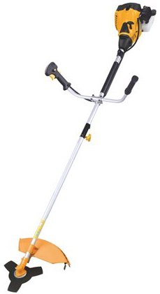
My 29.9cc 2-Cycle Gas-Powered Straight-Shaft String Trimmer with Split Shaft died on me a year ago (full story HERE)
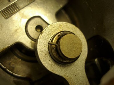
Cause of death was a broken securing pin
That found its way between piston and cylinder and distroyed the piston.
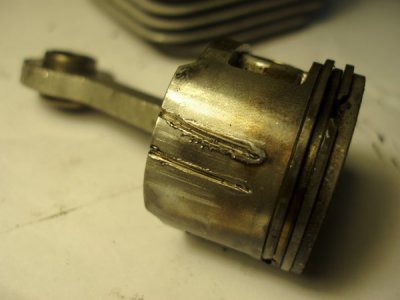
Instead of throwing the trimmer away (and miss all the fun) I decided to keep it and experiment with a piston replacement project.
As the cylinder was usable (with scratches though) and the old piston was beyond repair I tried to find a replacement piston.
Original piston measurements:
Diameter 36.36mm
Height 28mm (top to bottom skirt)
Top to wrist pin center 16mm
8mm wrist pin
Nearest piston I found at e-bay was:
A “37MM Piston Kit With Ring For STIHL 017 MS170”
37mm diameter.
30 mm height.
Unknown Top to wrist pin center distance (I estimated from the photo that it was close).
8mm wrist pin.
Cost $6 including postage from Hong Kong.
So I bought it to have a go at trying to make it fit.
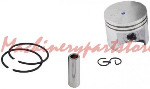
When the piston arrived and I measured it was close to what I needed!
Top to wrist pin center distance 16.5mm (need to be 16mm).
Diameter 37 mm (need to be 36.36mm).
The piston will need a bit machined off the top of it and all around.
The problem I had was how I could hold it on the lathe to do the machining.
A quick look at the Internet revealed some diy very sophisticated devices to hold a piston from the wrist pin to the chuck.
Nice but far too complicated!
Not to mention that I do not trust the chuck for such a work...
I prefer the faceplate not the chuck for a work like that.
I thought that I can use the “hold from the wrist pin” principle but in a simple way.
A piece of 10mm pipe threaded M8 at one end, made flat at the other end and drilled 8mm for the wrist pin will work just fine to hold the piston securely on the faceplate.

To machine all around the piston to bottom without scratching the faceplate an aluminum washer will give the necessary clearance.
So all parts needed were available and ready to be placed on the lathe.

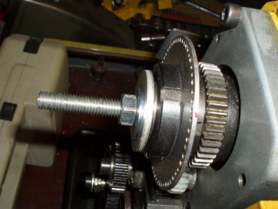
The rod will go through the spindle, washers and nut at the back...
the aluminum washer and the piston at the faceplate.
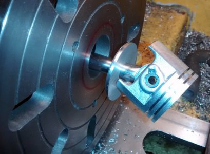
To minimize the play of the pipe on the wrist pin I added two extra washers to the pin.
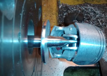
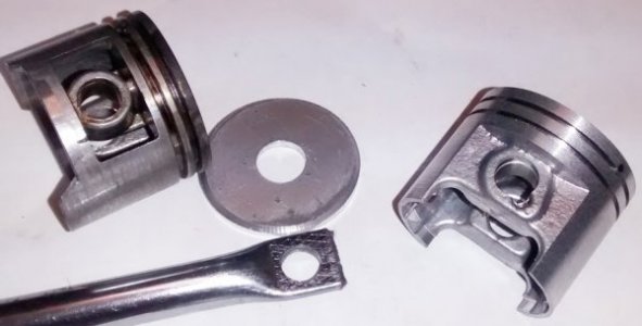
The completed setting looks like this.
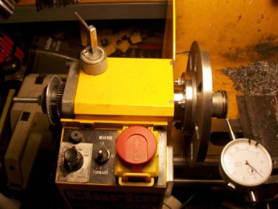
The hardest part was to make the piston running true.
I hand-tighten the nut, then using a soft-blow hammer I taped the piston with it till it was running true and then fully tighten the piston on the plate (at the following photo is the old piston I used to try the setting).
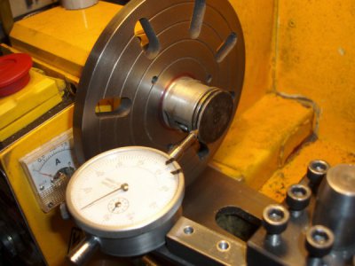
I skimmed 0.50 mm off the top of the piston and 0.64mm off around it.
I know that pistons are not supposed to be cylindrical but I could not make any accurate measurements to the original one to tranfer it to the new piston.
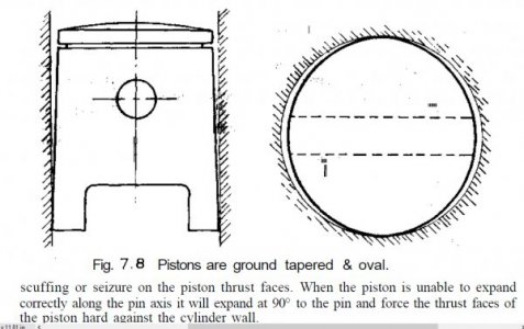
I also shortened the rings (using my dremel) according the size of the original ones

...and put the piston-rings assembly back to the cylinder.
Here the Piston is at BDC.
You can see the top of it exposed through the exhaust port.
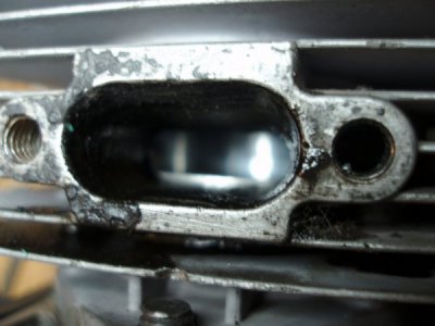
Some piston mod will be in order after testing that the engine works....
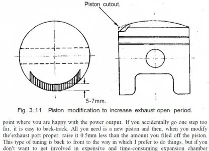
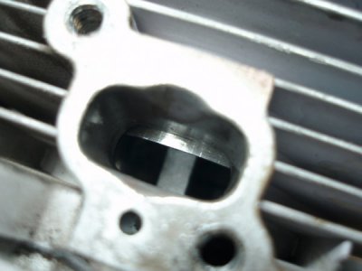
Similarly when the piston is at TDC the intake port is not fully opened.
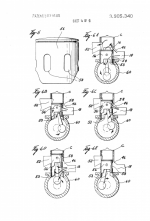
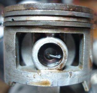
The original piston was shorter at the intake side (Lower left at the following pic).
So after testing the engine some fine tuning will be in order.
Thanks for reading
Petros
To be continued...

Cause of death was a broken securing pin

That found its way between piston and cylinder and distroyed the piston.

Instead of throwing the trimmer away (and miss all the fun) I decided to keep it and experiment with a piston replacement project.
As the cylinder was usable (with scratches though) and the old piston was beyond repair I tried to find a replacement piston.
Original piston measurements:
Diameter 36.36mm
Height 28mm (top to bottom skirt)
Top to wrist pin center 16mm
8mm wrist pin
Nearest piston I found at e-bay was:
A “37MM Piston Kit With Ring For STIHL 017 MS170”
37mm diameter.
30 mm height.
Unknown Top to wrist pin center distance (I estimated from the photo that it was close).
8mm wrist pin.
Cost $6 including postage from Hong Kong.
So I bought it to have a go at trying to make it fit.

When the piston arrived and I measured it was close to what I needed!
Top to wrist pin center distance 16.5mm (need to be 16mm).
Diameter 37 mm (need to be 36.36mm).
The piston will need a bit machined off the top of it and all around.
The problem I had was how I could hold it on the lathe to do the machining.
A quick look at the Internet revealed some diy very sophisticated devices to hold a piston from the wrist pin to the chuck.


Nice but far too complicated!
Not to mention that I do not trust the chuck for such a work...
I prefer the faceplate not the chuck for a work like that.
I thought that I can use the “hold from the wrist pin” principle but in a simple way.
A piece of 10mm pipe threaded M8 at one end, made flat at the other end and drilled 8mm for the wrist pin will work just fine to hold the piston securely on the faceplate.

To machine all around the piston to bottom without scratching the faceplate an aluminum washer will give the necessary clearance.
So all parts needed were available and ready to be placed on the lathe.

The rod will go through the spindle, washers and nut at the back...

the aluminum washer and the piston at the faceplate.

To minimize the play of the pipe on the wrist pin I added two extra washers to the pin.

The completed setting looks like this.

The hardest part was to make the piston running true.
I hand-tighten the nut, then using a soft-blow hammer I taped the piston with it till it was running true and then fully tighten the piston on the plate (at the following photo is the old piston I used to try the setting).

I skimmed 0.50 mm off the top of the piston and 0.64mm off around it.
I know that pistons are not supposed to be cylindrical but I could not make any accurate measurements to the original one to tranfer it to the new piston.

I also shortened the rings (using my dremel) according the size of the original ones

...and put the piston-rings assembly back to the cylinder.
Here the Piston is at BDC.
You can see the top of it exposed through the exhaust port.

Some piston mod will be in order after testing that the engine works....

Similarly when the piston is at TDC the intake port is not fully opened.

The original piston was shorter at the intake side (Lower left at the following pic).

So after testing the engine some fine tuning will be in order.
Thanks for reading
Petros
To be continued...
Last edited:


