- Joined
- Apr 21, 2015
- Messages
- 653
Embarrassing as this was, I'm posting this in the hopes that it might help someone else.
Tl;dr version:
My rear spindle nut was nowhere near tight enough, so the spindle assembly wasn't under sufficient tension. After making a dedicated tool to tighten the nut, I was able to reduce about +/- 0.005" of play at the front of the spindle to +/- 0.0004" (better than a 10x improvement).
Long version:
I bought my first (and only) lathe a couple years ago (11" Montgomery Wards/Logan PowerKraft 2130 circa 1941). As with any new hobby, there was a pretty significant learning curve, and I learned a ridiculous amount just correcting my various mistakes. I learned that nine times out of ten any problems I experienced were due to something I'd done wrong (dull tools, tool not at center, poor tool grinding angles for the material, poor work-holding, whatever).
Ten times out of ten I'd blame the tools first, of course.
Anyway, as I gained experience I was becoming increasingly frustrated with the amount of chatter when parting, boring, or taking heavy turning cuts. I became fairly skilled at taking light cuts and playing with speeds and feeds — I made plenty of parts accurately, if slowly, and with a fair amount of cursing along the way.
Parting was a particular headache. I spent a lot of time sharpening and honing, tightening gibs, minimizing tool and part hang-out, carefully squaring my tool, carefully checking that it's just a smidge below center height, and adjusting speeds and feeds. Still, most of the time I was getting excessive chatter, even with soft stuff like aluminum and bronze. I'd break out in a victory dance on the rare occasion that I was able to part smoothly.
The problem was particularly bad when using my large (heavy) 6-jaw chuck. Quite a while back I decided to replace the spindle bearings in the hope that that was the problem. In my defense, I relish every opportunity to take apart and learn more about my lathe (I'd never pulled the spindle before).
I ended up removing and replacing the spindle multiple times as I made various bone-headed mistakes (only a complete idiot would put the spindle back on before putting on the new serpentine belt he purchased expressly for the opportunity). I noticed that when I first took out the bearings, the front (tail-stock side) bearing took quite a bit of force to press out of the headstock, but on the final re-assembly (after two or three remove/re-install cycles) I could actually push it back into place with just finger force (significant finger pressure to be sure, but quite a bit looser than originally).
The new bearings did seem to help, but it was only a modest improvement. I still had to baby my cuts.
Finally I got smart and decided to measure things. I took off the chuck, and put a fairly hefty (3/4") drill with a morse taper shank directly into the MT3 spindle (I did need a MT2-to-MT3 adapter). Then I measured the deflection right at the tip of the spindle nose as I pushed and pulled on the drill bit (with a fair amount of force).
I could easily get plus or minus 0.005" deflection without undue pressure. This sure seemed like a lot, especially compared to tool and part stiffness, but with so little experience and such an old lathe I wasn't sure if it was excessive. I did know that chatter means something isn't sufficiently rigid.
Jim Sehr was kind enough to measure his lathe and he only saw a few tenths of deflection at the nose. Now I knew for certain that I had a problem, but I wasn't sure if it was something I could fix. I was worried that I had a clapped out lathe and that removing/inserting the spindle so many times scraped enough metal in the headstock to cause the play. If that was the problem, the only "solution" I could imagine was brazing on some more material into the headstock, and re-boring the holes for the bearings — a far larger task than I was comfortable tackling.
Fortunately, I read somewhere that the spindle is supposed to be in tension (I wish I could remember where I saw this — I'd like to thank whoever mentioned it).
The nut at the rear end of the spindle is just a ring with a hole for a pin-spanner: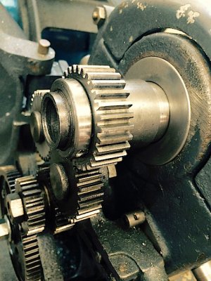
I don't remember exactly how I removed that nut or re-tightened it when I first removed the spindle. I remember that I had to jury-rig something because the pin-spanners I owned all had a pin too large for that hole. Somebody on this forum or on the Logan lathe mailing list periodically suggests making a dedicated collar with a grub screw to remove/tighten this nut when removing the spindle. I don't remember whot it was, but thank you whoever you are!
It certainly seemed tight, but I wondered if I could tighten it further. So I built this tool out of some scrap aluminum:
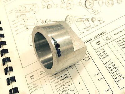
I turned down the end of the grub screw so it fit into the pin-hole on the nut. The flats on the back of the tool let me use a big adjustable wrench to crank the nut tight. Aluminum is pretty soft for this purpose, but it sufficed for one-time use (the grub screw had wallowed out the tapped hole a bit after I used it).
Here it is on the nut, with the grub screw engaged:
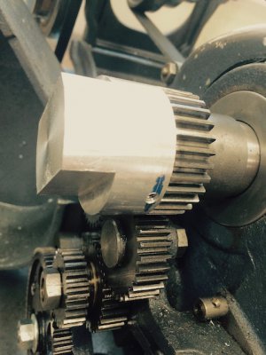
I was surprised to discover that I could get a bit more than one full turn on the nut with this tool (I'm pretty sure it is now tighter than it was when I originally received the lathe, before I replaced the bearings). I was extremely happy to discover that tightening this nut reduced the amount of play at the nose quite significantly (by a factor of ten).
I haven't done a lot of work yet since making the adjustment (just a few bits of aluminum) but so far I've had no chatter whatsoever, even with very heavy boring-bar cuts. What an improvement!
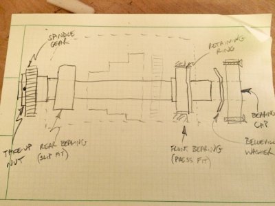
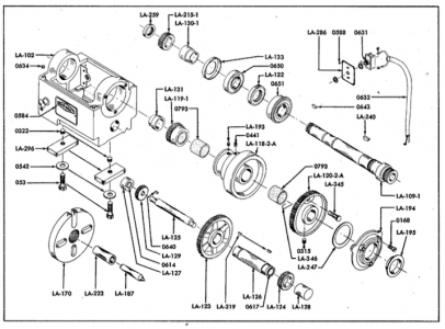
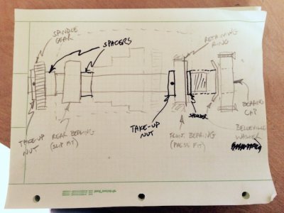
I don't quite understand the physics of why this should make such a difference. The rear (left, headstock-end) bearing on a Logan is a close-tolerance slip-fit. The front bearing is a press-fit. All I can figure is that cranking down on the nut locks the rear bearing to the rest of the spindle better. I suppose it's like bolt-on legs on a table, unless you really crank down on the bolts all the little micro-slippages add up to a wobbly table. Welded on legs are infinitely more rigid than bolt-on legs no matter how much you tighten the bolts.
If anyone has a better explanation, I'd love to hear it.
Anyway, I hope this might help someone else in the future.
--
Rex
Tl;dr version:
My rear spindle nut was nowhere near tight enough, so the spindle assembly wasn't under sufficient tension. After making a dedicated tool to tighten the nut, I was able to reduce about +/- 0.005" of play at the front of the spindle to +/- 0.0004" (better than a 10x improvement).
Long version:
I bought my first (and only) lathe a couple years ago (11" Montgomery Wards/Logan PowerKraft 2130 circa 1941). As with any new hobby, there was a pretty significant learning curve, and I learned a ridiculous amount just correcting my various mistakes. I learned that nine times out of ten any problems I experienced were due to something I'd done wrong (dull tools, tool not at center, poor tool grinding angles for the material, poor work-holding, whatever).
Ten times out of ten I'd blame the tools first, of course.
Anyway, as I gained experience I was becoming increasingly frustrated with the amount of chatter when parting, boring, or taking heavy turning cuts. I became fairly skilled at taking light cuts and playing with speeds and feeds — I made plenty of parts accurately, if slowly, and with a fair amount of cursing along the way.
Parting was a particular headache. I spent a lot of time sharpening and honing, tightening gibs, minimizing tool and part hang-out, carefully squaring my tool, carefully checking that it's just a smidge below center height, and adjusting speeds and feeds. Still, most of the time I was getting excessive chatter, even with soft stuff like aluminum and bronze. I'd break out in a victory dance on the rare occasion that I was able to part smoothly.
The problem was particularly bad when using my large (heavy) 6-jaw chuck. Quite a while back I decided to replace the spindle bearings in the hope that that was the problem. In my defense, I relish every opportunity to take apart and learn more about my lathe (I'd never pulled the spindle before).
I ended up removing and replacing the spindle multiple times as I made various bone-headed mistakes (only a complete idiot would put the spindle back on before putting on the new serpentine belt he purchased expressly for the opportunity). I noticed that when I first took out the bearings, the front (tail-stock side) bearing took quite a bit of force to press out of the headstock, but on the final re-assembly (after two or three remove/re-install cycles) I could actually push it back into place with just finger force (significant finger pressure to be sure, but quite a bit looser than originally).
The new bearings did seem to help, but it was only a modest improvement. I still had to baby my cuts.
Finally I got smart and decided to measure things. I took off the chuck, and put a fairly hefty (3/4") drill with a morse taper shank directly into the MT3 spindle (I did need a MT2-to-MT3 adapter). Then I measured the deflection right at the tip of the spindle nose as I pushed and pulled on the drill bit (with a fair amount of force).
I could easily get plus or minus 0.005" deflection without undue pressure. This sure seemed like a lot, especially compared to tool and part stiffness, but with so little experience and such an old lathe I wasn't sure if it was excessive. I did know that chatter means something isn't sufficiently rigid.
Jim Sehr was kind enough to measure his lathe and he only saw a few tenths of deflection at the nose. Now I knew for certain that I had a problem, but I wasn't sure if it was something I could fix. I was worried that I had a clapped out lathe and that removing/inserting the spindle so many times scraped enough metal in the headstock to cause the play. If that was the problem, the only "solution" I could imagine was brazing on some more material into the headstock, and re-boring the holes for the bearings — a far larger task than I was comfortable tackling.
Fortunately, I read somewhere that the spindle is supposed to be in tension (I wish I could remember where I saw this — I'd like to thank whoever mentioned it).
The nut at the rear end of the spindle is just a ring with a hole for a pin-spanner:

I don't remember exactly how I removed that nut or re-tightened it when I first removed the spindle. I remember that I had to jury-rig something because the pin-spanners I owned all had a pin too large for that hole. Somebody on this forum or on the Logan lathe mailing list periodically suggests making a dedicated collar with a grub screw to remove/tighten this nut when removing the spindle. I don't remember whot it was, but thank you whoever you are!
It certainly seemed tight, but I wondered if I could tighten it further. So I built this tool out of some scrap aluminum:

I turned down the end of the grub screw so it fit into the pin-hole on the nut. The flats on the back of the tool let me use a big adjustable wrench to crank the nut tight. Aluminum is pretty soft for this purpose, but it sufficed for one-time use (the grub screw had wallowed out the tapped hole a bit after I used it).
Here it is on the nut, with the grub screw engaged:

I was surprised to discover that I could get a bit more than one full turn on the nut with this tool (I'm pretty sure it is now tighter than it was when I originally received the lathe, before I replaced the bearings). I was extremely happy to discover that tightening this nut reduced the amount of play at the nose quite significantly (by a factor of ten).
I haven't done a lot of work yet since making the adjustment (just a few bits of aluminum) but so far I've had no chatter whatsoever, even with very heavy boring-bar cuts. What an improvement!
I don't quite understand the physics of why this should make such a difference. The rear (left, headstock-end) bearing on a Logan is a close-tolerance slip-fit. The front bearing is a press-fit. All I can figure is that cranking down on the nut locks the rear bearing to the rest of the spindle better. I suppose it's like bolt-on legs on a table, unless you really crank down on the bolts all the little micro-slippages add up to a wobbly table. Welded on legs are infinitely more rigid than bolt-on legs no matter how much you tighten the bolts.
If anyone has a better explanation, I'd love to hear it.
Anyway, I hope this might help someone else in the future.
--
Rex


