Drum switch wiring help

the westinghouse 316P is not a capacitor start or a capacitor run motor.

safety switches break the neutral leg on many pieces of equipment.
you aren't shutting off the equipment merely reversing direction, disconnect is done by the equipment's start/stop switch
 
well I am getting much needed help and fully understand the posting by ulma doctor as where to connect the wires... can anyone agree thats how I should do this or can anyone be simple like his post as to where to connect my wires..thanks the pictures are all I have to go on motor pic switch pic and motor spec pic ....
 
the westinghouse 316P is not a capacitor start or a capacitor run motor.

safety switches break the neutral leg on many pieces of equipment.
you aren't shutting off the equipment merely reversing direction, disconnect is done by the equipment's start/stop switch

don't forget 50% of the Alternating Current cycle the neutral wire is hot(conducting).
 
Last edited:
the westinghouse 316P is not a capacitor start or a capacitor run motor.

You're right. But it's still a two winding motor. As far as I can tell you're leaving one winding powered.

safety switches break the neutral leg on many pieces of equipment.
you aren't shutting off the equipment merely reversing direction, disconnect is done by the equipment's start/stop switch

The center position of a drum switch is expected to be OFF. I can't tell for sure without a diagram for that switch, but it appears to me that your circuit will disconnect the red-black winding when the switch is centered and leave the other winding powered.
 
well I am getting much needed help and fully understand the posting by ulma doctor as where to connect the wires... can anyone agree thats how I should do this or can anyone be simple like his post as to where to connect my wires..thanks the pictures are all I have to go on motor pic switch pic and motor spec pic ....


most people age going to tell you that you can't and you shouldn't all through out your life.
don't be discouraged, there are ways of accomplishing things when you listen to people who wish to help out in attaining your goal,
rather than telling you how you can't attain your goal and don't attempt.
 
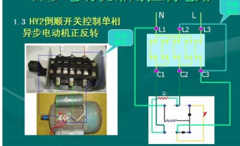
this is the wiring diagram the seller sent me does this help understand the switch

Motor wiring diagram.png
 
don't forget 50% of the Alternating Current cycle the neutral wire is hot.

No it isn't. On a US single-phase service the neutral is tied to ground at the service entrance. The neutral is a current carrying conductor but the only voltage on it with respect to ground is the voltage drop due to the impedance of the wire from the point of measurement to the point where it is grounded. In a 120V circuit the instantaneous voltage between the neutral and the hot varies sinusoidally between +170 and -170, giving an RMS voltage of 120.
 
tawas,

The motor is probably a split-phase type made for fans and other low starting torque applications. This thread isn't going anywhere useful until/unless we have the switch connection diagram. This is usually to be found on the inside of the removable switch box cover. If you can photograph that and attach it, I can tell you how to slightly modify the motor and how to connect it and the single-phase 115 VAC line to the switch.

Otherwise, you are probably best served by taking the motor and switch (with cover) to someone local who can figure it out.

I'll add that a 1/4 HP motor is on the light side for the 6" Atlas. And being of open construction, you will have to be careful not to allow swarf to be thrown into it. A better choice would be a 1/3 HP TEFC.

Robert D.
 
this is the wiring diagram the seller sent me does this help understand the switch

That would help a lot if I could read it. Unfortunately the switch diagram is illegible. Do you have a manufacter's name and model number for the switch? Or a better picture of the diagram?
 
tawas (& John),

I enhanced the switch diagram you just sent while I was writing my previous as much as I could. I can make out the five internal switch contacts across the bottom (near C1/2/3 and the first and fifth top ones nearest L1/3. But the internal connections to the center three top ones is still just a blur. Plus there is also no indication on the diagram of which switches close when you move the switch lever off-center in either direction. On might guess that (numbering the switches from left to right) that 1, 3 & 5 close in one direction and 2, 4 & 5 in the other. But that's only a guess and even if correct, the connections between 2, 3 & 4 are illegible.

If this is the only diagram you have (even if it is actually for the switch you have as the diagram says L1, L2, L3 whereas the switch is actually marked N1, N2, N3), what can be read doesn't answer enough questions to be able to safely proceed.

As I wrote earlier, you had better take it to someone who knows how to figure it out.

Robert D.
 
Back
Top