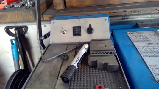
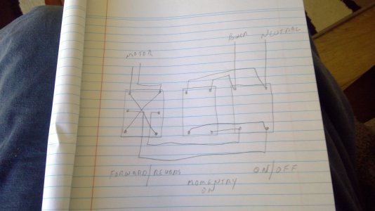
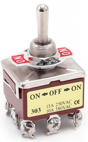
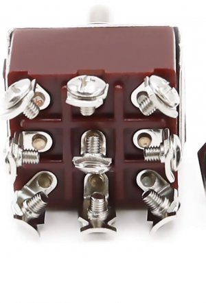
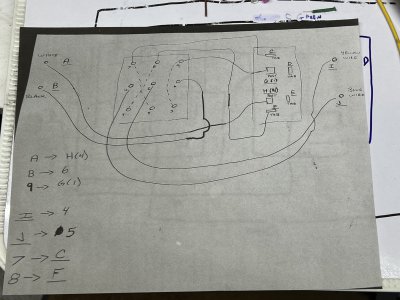
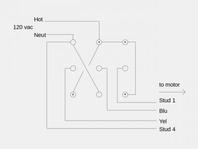
Something to throw in here- I see the wiring is covered, but I have an observation. Having "converted" a couple of drill presses to utilize a reversible, but not "instant reversing" motor-
Don't rule out the much simpler two switch options. Leave the main power switch as it is, and set up a second to swap the start wires. You'll still be waiting on the motor to stop after you've flipped four switches. Two switches (in this use case) is not so much of an imposition as you would think it is. It also serves as a "reminder" in the first few (days? months? years?) that you've modified it, whereas a single switch solution is very likely to get flipped too quickly. Not that it'll hurt the motor, it won't, but it's frustrating until you've trained your muscle memory.
Having an "OFF" position in both switches is a good thing. It lets you "double safe" the machine very easily, short of actually unplugging it, if that sort of thing is entertaining to you. (Unplugging is NEVER a bad option...) Not so much for changing a drill bit, but maybe belt services, lubrication, adjustments, and such where you're simultaneously not paying attention to the routine operation, AND doing things where you really might actually "bump" into a switch...
Again, just observations and food for thought from having done it. I like two switches, but there's a lot of ways to skin this cat. That's my experience.

