Dividing Head Question Bonanza

You have to hand it to the Medieval craftsman to design a working gear without the aid of CAD or complicated mathematics.

It does appear to be an easy design on the surface. I only built this one peg gear clock, and I basically built it just off the top of my head using simple obvious math. Without even really taking pin clearance into consideration much. I basically just focused on the pin spacing intuitively to make sure the pins didn't crash into each other. No fancy math. And it did work. It was binding up a little bit in certain places, but I think that was mainly due to lack of precision when drilling the pin holes.

These formulae you've pointed to account for pin length, and pin diameter, etc. You can get pretty carried away with these equations to design the best possible geometry. And that's what I would like to do just for fun and the learning process. This might be especially useful if I eventually move over to making metal pin or peg gears where it's best to get things right the first time through. With the wooden peg gears you can always do a little shaving or sanding where needed. That's a little more trouble with metal pins.

I'm just fascinated with antique technologies.

If you find anymore detailed information on making pin or peg gears I'd really appreciate it if you could post a link to it. These pin gears kind of caught my interest as novelty art. So it's something I'm looking forward to playing with. I've also recently become interested in building Stirling engings and Steampunk art. And so I might like to incorporate pin gears in those projects as well. It's all just for novelty and art.

The page you've provided is the best page I've seen yet in terms of giving some really nice equations to work with. Especially since that page addresses the 90 degree angle gears. I imagine there is probably more detailed info out there somewhere that addresses more complex pin gear configurations. I just haven't been able to find much.

Also, is there a difference between a "Pin Gear", and a "Peg Gear"? Or is that just interchangeable nomenclature? It's definitely an area of study I would like to read up on as much as I can. I'm looking forward to some day making metal pin gears, but I want to gain experience with wooden models first.
 
The model that I worked up would work too but there was an interference when the pin on one gear first made contact with the other gear. This was due to the previously engaged pin being closer to the axis of the other gear. It was apparent that for smooth operation, the length of the pins had to be considered. This explains it better than I did.
https://science.howstuffworks.com/transport/engines-equipment/gear1.htm

As to the nomenclature, I have heard both terms used for that type of gear. It seems that the term pin gear is used currently for a gear driven by an involute pinon rather than another pin gear. See also cage gears or lantern gears.
 
Well, I'm really excited about this first web page you linked to. This will basically allow me to design gears around the diameter of the dowel rods I have on stock. I currently have a large inventory of 3/8, 1/4, 3/16, and 1/8 dowel rods. (wooden). These are probably a softwood and would be better if they were hardwood. But this will be fine for prototypes.

So now I can design the gears starting with the pin diameters that I have. That will be my first self-imposed constraint. This will then determine the spacing required between the pins on any given gear.

In my case the height of the pegs is not critical as I can easily adjust for that by simply making the precise position of the gears adjustable. So on the pin length I'll only need to be in the ballpark.

The other self-imposed constraint that I'll be giving myself for right now, will be to use the 24-pin quick-indexing ring on the divider head. That's a restriction I don't really need to adhere to, but would like to stick with if possible.

My actual gear ratios aren't critical since they aren't involved in the timing of the clock. They are more associated with power and leverage considerations. So what I can do is choose the basic ratio diameters that I would like to have, and then go with whatever works out to be close to that ratio.

I can hardly wait to get started calculating!

I just came in from blowing snow. As soon as I take a bath and change my clothes I'll start designing gears based on the wood dowels I have.

Edited to add:

I just now figured out that with a 24 hole indexing plate I can have pin gears with 2, 3, 4, 6, 8, 12, or 24 pins. Not sure how well a 2-pin gear would work, but it's on the list. My original clock had 6 pins on the small gear and 20 pins on the large gear. I have no idea how I came up with that configuration. That was all done just intuitively.

So I might try two designs to start with. A 6-pin small gear, and try that with either a 12-pin or 24-pin gear. Apparently the same 6-pin gear would work on either of the other two sized gears. Also the 12-pin and 24-pin gears should mesh well too. The pin spacing is determined by the diameter of the pins, so the pin spacing will be the same on all the gears. That's kind of interesting to know. In other words I can just make up an assortment of gears based on these pin constraints and any two gears should then mesh together nicely. That's kind of cool. If it turns out to be that easy I'll be sure to get carried away with this. :grin:
 
Last edited:
A little digging turned up this
http://www.odts.de/southptr/gears/pegs1.htm
Enjoy!

I just have to thank you for finding this fantastic web page. It may not look like much, but it was precisely what I was looking for.

It took me a while to go through their equations to fully understand them. It was a tiny bit confusing because it wasn't crystal clear what some of their variables were representing exactly.

At the bottom of that web page they link to a "Calculation Sheet" which is actually a java program that will do the calculations for you for any size pins and gears you need. At first I was having difficulty with this because I wasn't fully understanding their "minimum dist" calculation. For some reason i was thinking this was them minimum distance between pin spacing on a gear. But clearly that couldn't be right. They I finally realized that this is the minimum distance between pins on different gears when they mesh. Then it finally all made perfect sense.

Also, their java program will only take limited parameters. So you can't really put in numbers for really "sloppy" gears. That was the other thing that threw me off. I was tossing in numbers that I knew would work, but they were simply out of range of what the programmer allowed for. Whoever wrote the program expects you to be designing some pretty close-tolerance gear evidently.

The other thing that was interesting is that they are assuming the pegs just touch or "bottom out" against the opposite gear base plate. And they take into consideration the actual height of the pins. Because of this the pins need to be really short. Less than the full diameter of the pin. Unlike their pictures where the pins are actually taller than their diameter. That still doesn't seem right. Most pin gears I've seen the pins are quite a bit longer than their diameter. The pins on my original clock were 1/4" pins but about 3/4" long. That makes for a very sloppy gear design, but it works. In fact, video I posted in post #2 of this thread uses pins that are far longer than their own diameter. But then again, it's probably not a very efficient design.

Finally, I'd just like to say that the actual pin length is basically unimportant as long as the gear position can be easily adjusted. When assembling all that would be required is to adjust how much of the pins mesh. That would take care of the pin length. The only difference is that the pins wouldn't bottom out against the base of the gear. Instead just the tips of the pins would be meshing. I'll most likely go with longer pins and just make the gear positions easily adjustable.

But this Java program needs to have short pins in order to do its calculations. It's going to assume that the pins "bottom out" when meshing. I guess to write the program the programmer had to have some means of referencing a "perfect adjustment". So just calculating for when the pins bottom out gives that rock solid reference point.

Anyway, it's 5:30 AM and now I can finally go to sleep. I got this all figured out. Tomorrow I can start designing some actual gears.

Thanks again for the quick reference to this wonderful webpage and pin gear calculator. That's exactly what I was looking for.

This saved me from having to figure this stuff all out from scratch.
 
The role of pin length in the design was the issue that I saw when I was modeling. I tried varying the spacing , pin diameter, and number of pins on the gear but couldn't make the interference go away.

There is a point in the rotation where the next or previous pins interfere.. This would be like little speed bumps in the rotation which would create a rumble to the motion. By shortening the pins, the previous/next pin would roll off the end, eliminating the interference. The result would be a smooth transition from pin to pin. what bothered me about it was that this would not be a reasonable method of transmitting any significant power due to the wear which would occur.

Modern gears engage multiple teeth at once, distributing the load and providing a smooth transition. The use of an involute pinon solves the problem with modern pin gears.

One thought that I had was to modify the pin ends to something like a bullet shape to provide a smooth transition of load between pins. This would actually be easier than making an involute pinion. It doesn't solve the high stress point issue but for a light load as in your application, could work.

If you haven't done so already, I would encourage you to look at Fusion 360 as a 3D CAD application. It is free for hobbyists and offers the ability model your gears and create assemblies and see the effect of making changes to your designs. It has a fairly steep learning curve but once you have passed that obstacle, you will find it to be a very powerful tool.
 
One thought that I had was to modify the pin ends to something like a bullet shape to provide a smooth transition of load between pins. This would actually be easier than making an involute pinion. It doesn't solve the high stress point issue but for a light load as in your application, could work.

Yes, I agree, it's easy to get carried away and try to "perfect" the peg gear system. But that really defeats its main quality which is simplicity. If we start shaping the pins into actual "teeth" we're really getting deep into "gear making" and leaving the original peg-gear simplicity behind. So yes, I too instantly thought of modifying the tops of the pegs to improve the design, but then instantly caught myself and said STOP! That actually introduces additional machining and manufacturing processes that the original peg-gear system was chosen to avoid. One of the reasons I'm going with peg gears is for simplicty of manufacturing. Just cut off a bunch of pegs to length, stick them into the holes in the wheel and your done. That one of the original attractions (along with the fact that I'm also keen on creating antique-like artwork).

So I've decided to go with unmodified pegs. None the less, I'd still like to design them to be as close in tolerance as possible. That's why I wanted these equations. This way I can actually design without having to resort to trial and error and I can shoot for the smallest amount of play tolerance that is practical for my manufacturing processes. I can already see that these equations are going to give me something far better than the original clock I had hacked together intuitively.

Also there are design considerations that must be acceptable.

1. The gears are best suited for unidirectional motion.

They can actually perform as bidirectional drives too, but there will be quite a bit of backlash slop during reversal. As long as that amount of slop is acceptable they can be used in bidirectional situations. But if the backlash slop is unacceptable then it's time to move on to better gears for that application.

2. The gears are best suited for light power transfer and probably low speeds too.

Again, these are limitations that fit the toys I'm building. Everything is extremely lightweight with no serious power involved, and the gears on my projects will also be turning an extremely low rates. High speed operation is certainly possible, but with wooden peg gears this may result in pegs wearing out very quickly, or even potentially heating up to combustible levels, and we certainly don't want that. Metal peg gears could be used for higher speed operations I imagine.

Since the above restrictions are acceptable for my intended purposes unmodified pegs should work just fine.

Like I say, I was thinking of cutting angles on the ends of the pins to accommodate closer tolerances and less backlash. But at that point I'd actually be making gear teeth. That defeats the original purpose of simplicy of manufacturing.

If you haven't done so already, I would encourage you to look at Fusion 360 as a 3D CAD application. It is free for hobbyists and offers the ability model your gears and create assemblies and see the effect of making changes to your designs. It has a fairly steep learning curve but once you have passed that obstacle, you will find it to be a very powerful tool.

I currently use Sketchup which has been serving me well thus far. Fusion 360 would need to offer some really useful additional features to make it worth my effort to re-learn a whole new CAD program. The only thing I would like to have that Sketchup doesn't have (at least not as far as I know), is an ability to animate the finished drawing. I can actually animate to a very limited degree with Sketch-up. In fact, I have also used Sketchup to make 3-D drawings, and then by simply taking screen shots of various different positions I was able to create animaged GIFs using the static 3-D drawings.

In fact, I'll be drawing up some gears in Sketchup here pretty shortly.
 
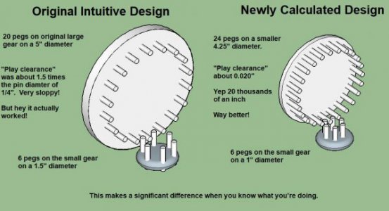
I designed the new gears for my clock. I drew up both the original gears that I hobbled together by intuitive feel versus the newly designed gears using the formulae provided by RJ. It's a world of difference! Now I can build clocks that are actually designed instead of just guessed at.

I went with 24 pins on the newly designed clock instead of the original 20 pins to accommodate my 24 hole dividing plate. If I would have stuck with the original 20 pins the new gear would have been even much smaller yet. But this is looking good.

I'm anxious to go out and build the new clock now. But it's like minus 2 degrees out in the shop right now. So maybe tomorrow.


Gears Compared.JPG
 
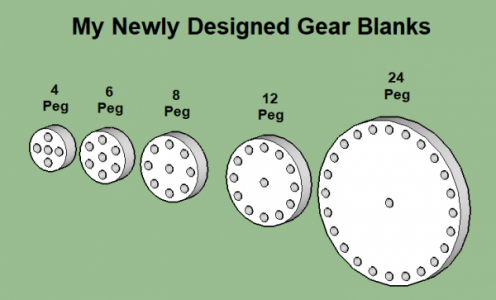
I just finished drawing up all the gears I'll be able to make with my current constraints.

Obviously the restriction of only making gears using the 24-hole quick-indexing plate is what kept this gear set small. If I remove that constraint and use the entire worm gear of the dividing head I can make gears of any peg count. But for right now I kind of like this constraint. I can just go out in the shop and set up to make these gears and then see what I can build with them. If I run into a situation where I want something different I can always lift these self-imposed constraints. These were all drawn up with 1/4 axle shafts too, but that would be easy enough to change on the fly.

I'm not sure if I'll ever actually use the 4-Peg gear, but you never know. It might come in handy as some kind of a counter, or idler between other gears. So I thought I'd draw it up anyway. The actual drawings include the dimensions. This whole thing is just to get my feet wet using this dividing head. Before too long I'll be moving up to making metal gears, and using the entire range of the dividing head. But this will be a great place to start. Any combination of these gears should mesh well together.


untitled.PNG
 
New Dividing Head Question?

How do I set up for 9 divisions?

I have a 40:1 worm gear dividing head with the following hole plates:

Plate A: 15, 16, 17, 18 ,19, 20
Plate B: 21, 23, 27, 29, 31, 33
Plate C: 37, 39, 41, 43, 47, 49

Can I use this to set up for 9 equally spaced divisions? And if so, which hole circle do I use?

Just to show how stupid I am I did the following calculation, but it didn't work.

40/9 = 4 & 4/9

Since 4/9 can be converted to 8/18 without flunking math, I naively thought that I could use the 18 hole circle on plate A.

I set it up and tried 4 whole turns plus 8 more holes for each division.

But it didn't work. At the end of the run it overlaps and wasn't divided evenly. So apparently I'm an idiot.

Unfortunately I'm not sure how to overcome my lack of intelligence.

I did find a YouTube video that said that to divide into 9 divisions I'll need a 36 hole plate. Is that true?

My dividing head won't do 9 equally-spaced divisions with the dividing plates I have?

That doesn't seem right. This must be far more complicated than I first thought.
 
Huh?

I just read the manual. (I always read the manuals after I can't figure out how something works). :grin:

The problem is that the manual is telling me to do precisely what I just did!

It says for a desired division T for 9 divisions, use the 18 hole plate, and 4 - 8/18 turns of the crank.

That's exactly what I'm doing? I must be counting the 8 extra holes wrong somehow?

untitled.JPG

Just for additional information I did this for 12 divisions and it worked just fine.

I did 12 divisions using 3 turns + 5 holes on a 15 hole circle and that worked out perfect.

And then I did it again using 3 turns + 6 holes on the 18 hole circle and it worked there too!

For some reason this doesn't seem to be working out when I try this for 9 divisions on 18 holes.

I'm doing 4 turns + 8 holes. That should work. The manual even verifies this should work.

I got to be doing something wrong. Maybe I should just go to bed and look at this fresh tomorrow.
 
Back
Top