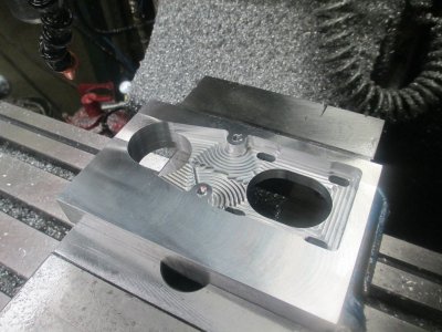
Digital Mist Coolant Pump

I'm not sure what the helix design gets you other than orienting the exit tubing in the same direction as the entrance tubing.
Lets you use one roller.

With multiple rollers it eliminates the eccentric shaft load and makes the load more uniform. It also works better when you can't fully occlude the tube. I've rarely seen it used, though. We never used it in the blood pumps.
 
I had a chance today to fine tune the operation and play with it a bit. I also have it integrated in to my software so it can be controlled manually on the screen or under G-code control. Delivery Rate is controlled with a mouse click on a slider bar. Flow can be controlled from about 1 drop per 10 seconds to a steady stream with very fine adjustment available over the entire range. This could also be done manually using a small DC gear motor and a PWM controller, available cheap from FleaBay.

How it works

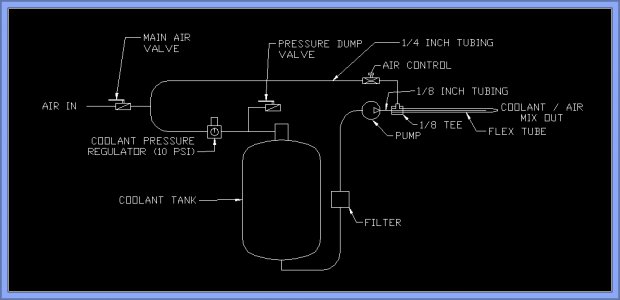
Here is a drawing of the major components and connections.
Coolant System.jpg

Because the original system used air pressure to dispense the fluid, I didn’t bother to change tanks. Since the pressure tank is sealed, it needs a vent so I am just pressurizing it to 10 PSI since the hardware is already installed. The new system could operate without the pressure tank, in fact you could just drop the intake hose to the pump into a bucket of coolant and the system would work fine.

In the drawing it shows manual valves to turn the air on and dump air from the tank, where in this case I am using a solenoid valve on the main air and a quick exhaust valve to dump the air off of the tank any time the solenoid is turned off.

The tank is a 20 lb sand blaster tank is from HF the rest of the components are available from many vendors. Small peristaltic pumps are available on FleaBay, or it’s a fun project to build one. If you haven’t read the first post in this thread, you might want to, it explains why I went this way. http://www.hobby-machinist.com/threads/digital-mist-coolant-pump.40405/

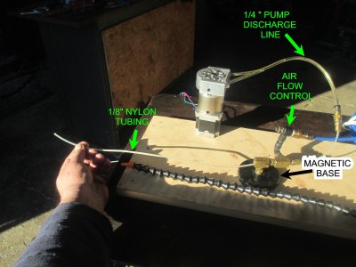
Here are the flow end components:
IMG_0613.jpg
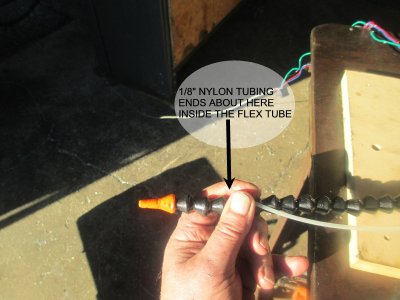
And the working end showing the relative length of the 1/8 inch nylon tube
IMG_0615.jpg

And a close up of the air plumbing. In order to get the 1/8 inch tube through the compression fitting, I had to run a 1/8 drill through it to open it up a bit. Didn’t seem to hurt the compression at all. I was mixing the fluid and air at the Tee, but I found it works better if you extend the nylon tube down the flex tube to near the end.
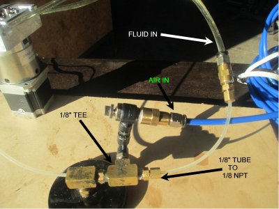
IMG_0616.jpg


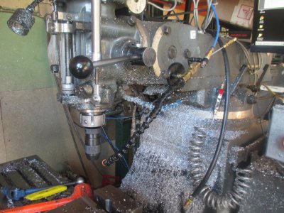
And installed on the mill (Tomorrow is clean up day:rolleyes:)

IMG_0617.jpg

The coolant tank, it holds about 3.5 gallons
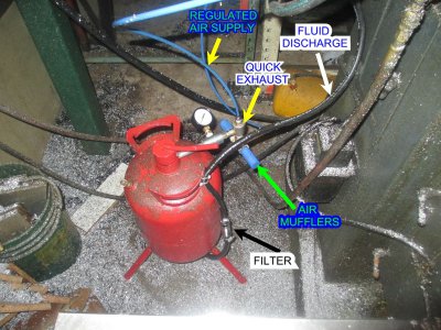
IMG_0628.jpg

The solenoid valve and tank pressure regulator
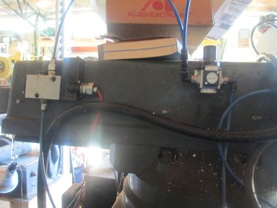
IMG_0620.jpg

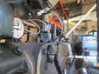
The pump in it’s new home on top of the ram. The ram on this mill has a nice wide flat top and sides, lot’s room to mount stuff. (The air cylinder above the pump is the quill counterbalance cylinder.)
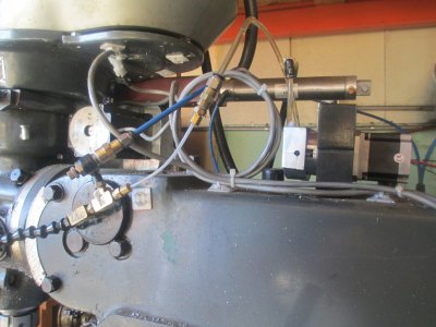
IMG_0623.jpg

The front view

IMG_0624.jpg

It’s really hard to get a picture of flowing droplets but here it is at about 10%
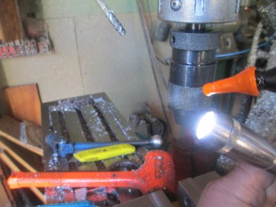
IMG_0629.jpg

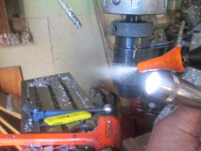
and at about 50% It puts out a nice micro droplet spray, but no fog.:encourage:

IMG_0630.jpg


.
 
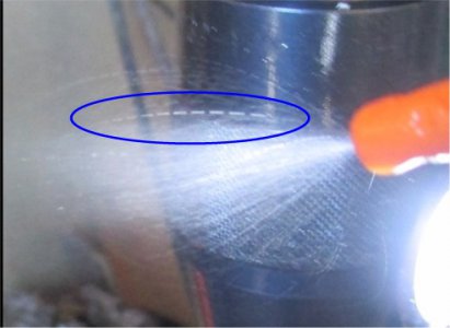
An interesting artifact in the above photo is this dashed ''line''. Took me a while to figure out what it is. I was using a LED MagLite to back light the spray. The MagLite has some electronics in it that strobes the output, so what you see is a motion blurred droplet when using a relatively slow shutter speed, and a high speed strobe. Kinda cool!

IMG_0630B.jpg
 
really cool work Jim - if you can't/ don't want to buy it, make it! I'm not sure what you ended up with for the secret anti-pulse sauce - multiple rollers? ie. lots of little pulses? Or something fancy in the stepper controller? But a mechanical idea might be to have some kind of partial flow impedance timed to the rollers in the pump, so that back pressure from the impedance reduced the peak pressure from each roller. Probably unnecessary, but it's an interesting thought experiment.

oh and the strobing from the LED light might be from PWM modulation of output - it's a common way to reduce drive current to an LED.
 
An interesting artifact in the above photo is this dashed ''line''. Took me a while to figure out what it is. I was using a LED MagLite to back light the spray. The MagLite has some electronics in it that strobes the output, so what you see is a motion blurred droplet when using a relatively slow shutter speed, and a high speed strobe. Kinda cool!

View attachment 115275

LED's all strobe, even when run off a non switching supply. You can shake your hand near the lights to evaluate them for flickyness, I have definetly noticed a difference between brands and styles of construction.

Don't do it in shops though you just look mad :)

Stuart
 
But a mechanical idea might be to have some kind of partial flow impedance timed to the rollers in the pump, so that back pressure from the impedance reduced the peak pressure from each roller.

Great minds think alike Matt. :)

On another note: The pump system works as expected :encourage: I was able to walk away for 63 minutes while this part ran.

Part of my next project, I'll post a build log tomorrow.

IMG_0640.jpg
 
Last edited:
LED's all strobe, even when run off a non switching supply. You can shake your hand near the lights to evaluate them for flickyness, I have definetly noticed a difference between brands and styles of construction.

Don't do it in shops though you just look mad :)

Stuart
LED's don't strobe if they are run off pure d.c. as in a battery or off a well filtered power supply. Many commercial supplies don't bother to filter well and LED's have short enough response time to act as a strobe. Additionally many LED drivers that have dimming capability use pulse width modulation technology which does turn the LED off and on at the modulation frequency.

What many people don't realize is that white LED's are actually fluorescent devices. The phosphors are being excited by the blue LED underneath instead of a mercury vapor discharge. All phosphors have a persistence which means that the phosphor continues to glow for a short time after the energization source has been removed. I have not done any measurements as to the actual persistance but it is apparently somewhere on the order of 10 msec.

Bob
 
Jim, a great project. You can take pride in the fact that you have addressed a problem in a novel way and successfully executed and implemented the solution. The great thing is that every time you use it, that feeling will come back.
:aok:

Bob.
 
Jim, a great project. You can take pride in the fact that you have addressed a problem in a novel way and successfully executed and implemented the solution. The great thing is that every time you use it, that feeling will come back.
:aok:

Bob.

Thank you for the kind words Bob. I like the challenge of solving problems, gives me something to do in my spare time.;)
 
Great minds think alike Matt. :)

On another note: The pump system works as expected :encourage: I was able to walk away for 63 minutes while this part ran.

Part of my next project, I'll post a build log tomorrow

he he he. I have lots of ideas, just no time to implement them! Threads like these are a great way to keep the flame alight until I can get back out in the garage.
 
Back
Top