Differences And Types Of Dc Motors

The issue i've always had when looking to use DC motors has always been the transformer or power supply required to knock the voltage down.

Stuart
Sorry if i'm just being slow, is that a BLDC motor controller ? Or a pwm dc motor controller?

Stuart

Dunno for sure. Documentation doesn't spell it out in layman's terms.

Says good up to 60 CPM for cycle duty permanent magnet motors, so I'll guess pwm.

Graham's Cycletrol® Series DC adjustable speed controls provide rapid cycling capabilities, while offering higher reliability and lower maintenance compared to clutch/brake mechanisms. The Cycletrol Series consists of two product lines, the 150 Series rated for up to 60 cycles/minute and the C2000 rated for up to 30 cycles/minute.
COMMON FEATURES:
All Cycletrol digital logic inputs are optically isolated
Versatile logic allows direct interfacing with switches and push-buttons or solid state devices
LED function lights are easy-to-see indicators of control status
Transient protection by voltage clamping MOV's and RC networks protect power components against power spikes
Torque limiting by the Cycletrol's adjustable current limit provides motor and drive train protection in the event of machine overloads or jams
Heavy-duty aluminum chassis or NEMA 12 enclosures
The Cycletrol 150 is the fastest cycling DC motor control in the industry. On-board logic controls reduce costly external relays and timing circuits. The 150's reliability is exemplified by a two-year warranty.
Cycle rate up to 60 cpm allows quick, repetitive run/stop operation with cycling duty permanent magnet motors
Wide speed range with full torque available down to 9 rpm
Integral timer enables automatic cycling; eliminates external components and wiring
Start-up current (up to 400%) provides extra starting torque for fast acceleration
Solid-state dynamic brake circuit for faster response without the wear normally associated with a mechanical system
Magnetic circuit breaker standard on NEMA 12 enclosure models

I can get around with electrical work, but I'm no engineer. Perhaps one of the "electrogeeks" on the forum can shed some light on the specs.

:)
 
Great White -
I just looked on eBay and, amongst the many expensive units saw several that were under $80. All of them, however, were rated for a 1/8 to 1 horsepower motors. So be cautious. I've seen lots of treadmill motors that are (at least claim to be) in the 2.5 to 3 HP range. Check yours!
 
One consideration in choosing a DC brush motor with PWM vs. 3 phase with VFD is electrical noise. Because of the commutator switching at high current loads, a significant amount of RF noise is generated. If you plan to use a DRO, it could be a headache trying to eliminate the interference.
 
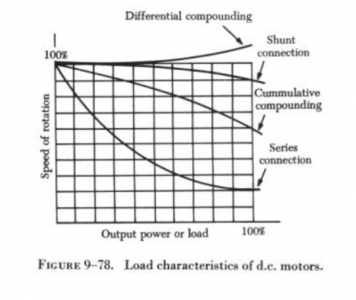
There are three basic types of dc motors: (1) Series motors, (2) shunt motors, and (3) compound motors. They differ largely in the method in which their field and armature coils are connected.

43e0162f-9ebe-41f3-ac07-21d86abf1d7b_zpspka74qi5.png
It appears that the axes are reversed in the above graph. Torque should be on the y axis and speed on the x. One should also understand that the graphs are normalized. A 1 hp differential compounded motor will have a lower low end torque than a 1 hp cumulative compounded motor.
 
Great article. Thanks for posting. I've been rebuilding starters and alternators for 34 yrs now and my understanding of how they work has been greatly enhanced by reading your posting. I've been considering the purchase of an old Heavy Duty LeBlond lathe that originally had a motor that would run at about 20 different speeds. It could be "shifted" electronically linearly from the apron. It has been converted to a 3 phase motor and a 4 speed transmission added to replace the variable speed motor. I also have a 5 hp DC motor rated 180 to 240 volts. I had understood that the torque would be pretty close to 10 hp 3 phase. After reading your link, I now understand how that would be. I was considering using the 5hp on the LeBlond. It may be a little under powered, as the lathe is a 33" by 8'. but if worked would re-establish the way it was originally designed. If I purchase the lathe might be worth a try.

Thanks again for posting, Tim
 
One consideration in choosing a DC brush motor with PWM vs. 3 phase with VFD is electrical noise. Because of the commutator switching at high current loads, a significant amount of RF noise is generated. If you plan to use a DRO, it could be a headache trying to eliminate the interference.

No worries. Not a factor. This is only an old th42 its going on. I don't do extensive work on a lathe, just a few things for my cars and motorcycles.

Great White -
I just looked on eBay and, amongst the many expensive units saw several that were under $80. All of them, however, were rated for a 1/8 to 1 horsepower motors. So be cautious. I've seen lots of treadmill motors that are (at least claim to be) in the 2.5 to 3 HP range. Check yours!

Not too worried. Its an experiment as much as anything else.

:)
 
It appears that the axes are reversed in the above graph. Torque should be on the y axis and speed on the x.
The graphs are often presented that way. However, the horizontal axis should be labeled torque, not power. Power is the product of speed and torque.
 
The graphs are often presented that way. However, the horizontal axis should be labeled torque, not power. Power is the product of speed and torque.
Got it! It seemed strange at first, but if you think that torque is proportional to applied current, then speed would be the dependent variable. It also makes sense in that any d.c. motor has a maximum speed and that is where the applied torque equals the frictional losses, etc. Otherwise, the motor would keep on reving until it self destructed.
 
Got it! It seemed strange at first, but if you think that torque is proportional to applied current, then speed would be the dependent variable. It also makes sense in that any d.c. motor has a maximum speed and that is where the applied torque equals the frictional losses, etc. Otherwise, the motor would keep on reving until it self destructed.
That is exactly what large series motors will do if operated at full voltage with no load and no current limiting. Large shunt motors will also overspeed to destruction if you interrupt their fields when they are running at full speed with no load. However, with its field properly excited a shunt motor has a fixed no-load speed where the back emf due to generator action equals the applied voltage.
 
As I understand it, the runaway situation only presents itself with series wound motors, especially larger ones. The shunt motors are self limiting, as are the compound motors AFAIK.

My motor theory is in the distant past, it's something to do with back emf induced in the armature I think. And while I have no experience with DRO's (but I would like to ) but do have experience with RF interference, the brush noise is a definite consideration.

Most of the things that we do in our home shops that are not for profit ventures depend on the material on hand. So in that light, using a motor that you have is superior to not using a tool because you don't have the BEST motor.

I have found that large 3 phase motors are much easier to find than large single phase motors. And both of those are easier to find than large DC motors. A lot of the larger surplus DC motors were rated for fork lift service. In that use they drive a pump, which presents no radial load on the armature. Transferring 5 HP though anything that present a radial load would likely be a problem for long term survival of the motors bearings. I hate to build something around a part that will fail and then cause an major redesign...

paul
 
Back
Top