Cutting square shaped spiral

I am confused by the question, and I think others are as well? Do you intend to cut round or square bar stock? When you say "spiral" a standard thread comes to mind. Do you mean something else? The example you showed is a shallow groove in round stock. I would guess the pitch to be about 2TPI. If you want something like this example, the cutting force would not be very high. If this is a one-of part,, and the exact pitch is not critical (i.e.it is decorative) you could drive the lead screw with an independent motor and get something useful. Perhaps a geared hand drill? The ratio of the spindle rpm to the hand drill rpm would relate to the pitch.
 
If yo have a non gearbox lathe then you probably have more flexibility or the option to make a replacement gear "banjo" , if it's a quick change gear box lathe then you would have to figure out a way of changing the gear ration into the quick change box (like the metric/imperial gear change setups)

Stu
I have a gear head lathe pm1236.
If yo have a non gearbox lathe then you probably have more flexibility or the option to make a replacement gear "banjo" , if it's a quick change gear box lathe then you would have to figure out a way of changing the gear ration into the quick change box (like the metric/imperial gear change setups)

Stu
 
I am confused by the question, and I think others are as well? Do you intend to cut round or square bar stock? When you say "spiral" a standard thread comes to mind. Do you mean something else? The example you showed is a shallow groove in round stock. I would guess the pitch to be about 2TPI. If you want something like this example, the cutting force would not be very high. If this is a one-of part,, and the exact pitch is not critical (i.e.it is decorative) you could drive the lead screw with an independent motor and get something useful. Perhaps a geared hand drill? The ratio of the spindle rpm to the hand drill rpm would relate to the pitch.
Round bar stock. Literally cutting a thread, but with a very spaced pitch, so it looks like a spiral design running down the side
 
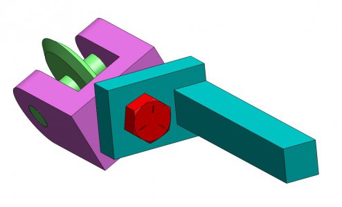
Here is another way a fast pitch spiral groove could be made on the lathe. A single wheel mounted on an axle which can be rotated in the vertical plane would create the helix angle. Varying the angle of the rotation would change the pitch.
Knurling Tool.JPG

I would set the carriage up for free travel, run the spindle at the slowest speed, and possibly assit the carriage travel with the hand crank.
 
Last edited:
Cutting any pattern on a square bar would require something like a CNC lathe, As the bar turns, the cutter would have to move in and out to track the surface. A CNC mill with a fourth axis could also cut this type of feature.

In woodworking there are pattern lathes that track a premade pattern to guide the cutter. This is how the curved legs on antique furniture are made.

On round stock the problem is gearing the lead screw such that it is turning faster than the spindle. If you were looking at a 1" pitch on the part and the lead screw has a pitch of 8 tpi, the lead screw will have to rotate 8 times for every spindle revolution. This would subject the lead screw and gearing well outside their design envelope. Modifying the lathe by using a fast pitch ball screw ( https://www.mcmaster.com/products/ball-screws/fast-travel-ball-screws-and-nuts/) would ease the situation but this isn't practical for a one off part.

Tom Lipton, OxTools, made a setup using an indexer (
) to accomplish this task on a manual mill. It uses an encoder driven by the x axis lead screw to send commands to a stepper which rotates the indexer in sync with the x axis travel to create the spiral.

Another option would be to use a spiral gear from an automotive differential or similar transmission to act as a knurling tool. You would have to make a custom setup to mount the gear rigidly on the cross slide. You would be limited to the pitch dictated by the helical gear though.
That makes sense, but I will have to just try cutting my lowest thread pitch my lathe will do and see what it looks like. I like that ball screw idea.
 
Here is another way a fast pitch spiral groove could be made on the lathe. A single wheel mounted on an axle which can be rotated in the vertical plane would create the helix angle. Varying the angle of the rotation would change the pitch.
View attachment 475613

I would set the carriage up for free travel, run the spindle at the slowest speed, and possibly assit the carriage travel with the hand crank.
Did you just model that in between us talking lol? impressive! What would allow the cutting to be done? Would the wheel be driven with a motor?
 
Did you just model that in between us talking lol? impressive! What would allow the cutting to be done? Would the wheel be driven with a motor?
Yes I did. That is why I love SolidWorks so much.

This will not cut the groove. It is essentially a single line knurling tool. The wheel is free wheeling just as a knurl is. In the actual tool, I would probably use ball or roller bearings rather than riding on the steel bores. The knurling wheel could be made to any form desired and if a square groove or round bottom groove was desired, that could easily be done.
Ok, I guess I exaggerated the engraving description. I want it deeper than a knurling tool. Do you see the cross drilling jig picture at the beginning of the thread. That guy had a similar spiral to what I want. How do you think he did that?
 
Ok, I guess I exaggerated the engraving description. I want it deeper than a knurling tool. Do you see the cross drilling jig picture at the beginning of the thread. That guy had a similar spiral to what I want. How do you think he did that?
I cut spirals like that when I move the carriage rapidly while not retracting the cutting tool. The trick is cutting a precision spiral. In order to do that, the lead screw has to somehow be synchronized with the spindle rotation. For threads, this is done through the gear train or with an electronic lead screw. The problem in cutting a fast , as stated earlier, is the pitch of the lead screw will require the lead screw to turn at a significantly higher rpm than than the spindle. This would be hard on the bearings in the gear box and for the lead screw. Obtaining a 8:1 or better increase in rpm would be difficult as well. For a lathe with a QCGB, it would have to be done with the external gear train. The largest pitch that your lathe can cut is 4 tpi so if you wanted to cut a 1 tpi helix, you would need to have an external 4:1 gear ratio between the the spindele and the input shaft to the gear box.

Assuming you were to do this in two stages and could split it more or less evenly, That would mean 2:1 on each stage. Your spindle gear has 48 teeth and if you drove the 120t gear, that would be a 3:1 reduction in speed. The second stage would need to provide a further 1.33 reduction or mor to be able to achieve thew overall 4:1 ratio. A further consideration would be the physical clearance. The sum of the number of teeth in the second stage will have to exceed 120 plus some in order to accomplish this. With the OEM gear set, you would probably have to use the 127t gear on the input shaft and one of the other gears on the banjo. You can the do fine adjustments using your QCGB.
 
Back
Top