Cutting metric threads on an imperial lathe

Thanks for the link.

I already have the 47/37 which is essentially the same.

This is just a guess, but I'm thinking 40/63 (I have a 40) will give some more usable thread combinations. The 10EE has a huge number of thread possiblities.

I plan to repeat my <very old> work on the 10EE with 47/37. This time get the math right. Then repeat with 40/63. If this works out the way I think it will, may look for a 60 and/or a 120 tooth. Make this decision once experimental results and the math line up.
 
If it helps this is how I did the maths for the metric thread chart.

Recalling that if an 8tpi leadscrew rotates at the same speed as the lathe spindle then you will cut an 8tpi thread on the work piece. If you want to cut a 16tpi thread then the speed of the leadscrew is reduced by 2, and for cutting a 24tpi thread the leadscrew speed is reduced by a factor of 3.

For metric threads the overall gear reduction ratio between the lathe spindle and leadscrew is given by:

Overall gear reduction = (25.4 / 8) x (1 / required metric pitch)

For a pitch of 1mm the overall gear reduction is simply:

O'all Red = 25.4 / 8 = 3.175 exactly.

If a compound gear set that approximates to 1.27 is used in the change gears (a set such as 47/37 or 80/63) then the second gear reduction ratio is:

Red2 = 3.175 / 1.27 = 2.5 exactly.

As a fraction 2.5 is 5/2. So gear combos of 50/20 or 75/30 or 100/40 would give that fractional ratio. So for example a 30 tooth gear on the tumbler output and a 75 tooth gear on the leadscrew gives the required fractional reduction.

From this single fraction for the 1mm pitch all the other fractions for various metric pitches can be derived. For a 2mm pitch thread the 1mm fractional ratio is reduced by 2 and becomes 5/4. For a 3mm pitch the 1mm fractional ratio is reduced by 3 and becomes 5/6.

A pitch of 1.5mm is mid way between pitches 1mm and 2mm and so the fractional ratio is mid way between 5/2 and 5/4, which is 5/3. A pitch of 2.5mm is mid way between pitches 2mm and 3mm and so the fractional ratio is 5/5.

A pitch of 1.5mm is twice 0.75mm and hence the fractional ratio for a pitch of 0.75mm is 2 x 5/3, i.e. 10/3.

And so on for the other pitches I listed previously. It is the fractional ratio that allows rapid selection of appropriate gears.
 
You're hired! (to help me with the maths on the 10EE) :)
 
OK, got the 63 tooth gear. DAMN it won't quite fit - a 60 tooth will.

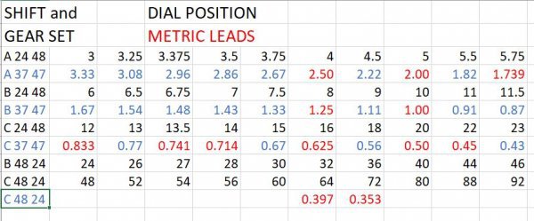
Decided to go ahead and make up a 10EE threading table with the 37/47 gear set I got from Logan Lathe.

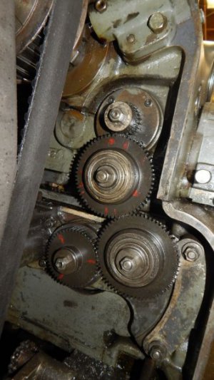
Pics of the thread gear train and thread dial attached. I installed a 37 tooth on top and the 47 tooth in the bottom position. Set the dial to A-5tpi and measured Z travel per ten revolutions => got 20mm. Repeated with dial set to B-10tpi and got 10mm per ten revolutions.

SOMEBODY PLEASE DOUBLE CHECK THIS. The math I get is 10/ US lead = metric lead in mm. I used this to make a new thread table. See pic and attached spread sheet. The blue numbers are pretty useless. RED with two digits is spot on for a metric lead. RED with three decimal places is the closest to a standard metric lead this machine can do.

A couple metric leads, 0.35 and 0.40, are actually closer with 48/24 gears in "C" range. AGAIN SOMEBODY PLEASE DOUBLE CHECK THIS.

EXTRA BONUS QUESTION for any math majors out there. I have a 48 tooth. If I replace the 47 with 48 (or even the 24) will any of the threads that do not quite match get closer to correct?


Metric thread table.JPG10EE theading gears.jpg10EE Threading dial.jpg
 

Attachments

  • Metric thread dial table.zip
    8 KB · Views: 7
Last edited:
Hello Karl. I googled '10EE' lathe and found a clip of Keith Rucker taking delivery of a Monarch 10EE lathe into his workshop. Wow, that lathe is definitely not your normal 10-inch swing bench lathe. What a beast.

I have looked at your data and pics and have a couple of queries and an observation.

Looking at your change gear pic, if we call the small gear at the top gear A and the other gears B, C and D (at the lower left of the set):
* can we assume that gear A rotates at the same RPM as the lathe spindle?
* is gear D the input to the gearbox?
* are gears A and D on fixed centres?
* are the centres of gears B and C adjustable?

If so then the only way I can make sense of your thread chart is if normally (for imperial threads) the 48 tooth gear is in position A and the 24 tooth gear is in position D. So the gearbox input runs at twice the RPM of gear A (and presumably the lathe spindle). If you then fit the 37 tooth gear to position A and the 47 tooth gear to position D, the gear box input RPM is slower than the spindle RPM and the numbers on your chart are correct.

It would appear that there is only a limited number of recognizable metric pitches to be found using the gear box. If you have a requirement for a specific metric thread then it might be possible to determine appropriate change gears for that one.

atb, Ian
 
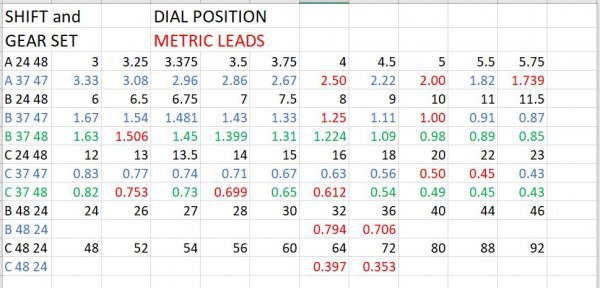
Played with a 37 48 combination. Worked the chart a bit more and came up with this, best that can be done with the gears on hand.
10EE Metric thread chart.JPG
 
I'm sorry, forgot to acknowledge your kind offer to help, above. Pretty sure I got it right.

yep glad I looked at the 37 48 combo cause .75 and 1.5 leads are pretty common. I only do hobby work, this is plenty good for my needs.
 
Karl, perhaps a final thought on cutting metric threads on your lathe with a QCGB.

As well as using gears such as 37-47 and 63-80 as spur gears to give a gear reduction that closely approximates to 1.27, the two gears can be mounted on a common shaft as a compound gear to give the magic 1.27 reduction.

If you mount the compound cluster in your change gear set in the lower RH position (which looks adjustable), fit a 50 tooth gear in the bottom LH position, then mount one of 3 gears with teeth 60, 50 or 35 in the top position, then that should give you the following metric pitches (mm):

4, 3, 2.5, 2, 1.75, 1.5, 1.25, 1, 0.8, 0.75, 0.6, 0.5, 0.35

All with the accuracy of the compound set 80/63 or 47/37.

So, with a 60T gear mounted in the top change gear position, the following gearbox selector positions (ABC and TPI) give metric pitches of:

A+3 = 4mm, A+4 = 3mm, B+3 = 2mm, B+4 = 1.5mm, C+3 = 1mm, C+3 3/4 = 0.8mm, C+4 = 0.75mm and C+5 = 0.6mm

A 50T gear mounted in the top change gear position gives:
A+4 = 2.5mm, A+5 = 2mm, B+4 = 1.25mm, B+5 = 1mm and C+5 = 0.5mm

A 35T gear mounted in the top change gear position gives:
A+3 1/2 = 2mm, A+4 = 1.75mm, B+3 1/2= 1mm, B+5 = 0.7mm, C+3 1/2 = 0.5mm and C+5 = 0.35mm.

Regards, Ian
 
Back
Top