Cross feed rate of travel

When boring the hole I did not move the compound and I was not using the compound to bore the hole. Only the cross feed.
This morning I set up a dial indicator and measured the movement of the cross slide. I did it in both directions and I did two complete revolutions in each direction. I took out the backlash before taking readings. One complete revolution of the cross feed dial moved the cross feed 0.100. I had the same amount of movement in both directions.

Based on Robert's post and my measurements this morning I should have only had to move the cross feed a total of .0625" to enlarge a 1/2" hole to 5/8." I am at a loss as to why I had to move the cross feed almost double this distance to enlarge the hole to 5/8." While I was boring the hole and it became apparent that I was moving the cross feed way more than I thought I should have to move it, I checked my set up over and over and could not find any thing amiss. I was not taking heavy cuts. The biggest cut I took was 0.005."

I have a mystery that I can't solve at this point. Maybe something will come to light when I enlarge the bore in the base plate from 1/2" to 5/8." I will use the exact same setup.
 
Depending on the boring bar and how sharp it is, the cuts you actually achieve can be much less than the amount dialed in. Use the most rigid setup and tooling possible, make sure that the cutter is sharp and the geometry and mounting is correct, look for possible rubbing below the cutting edge, and watch out when you get close, because spring in the tool can easily cause spring cuts to go too deep and ruin the job.
 
Another possible source of error is that the carriage gib is set too loose.
 
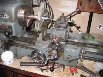
Here is a picture of my set up. Even though the compound and the cross feed are almost in alignment I only used the cross feed and never touched the compound.

IMG_3607.JPG
 
mickri, it's often the simplest things that cause the most frustration. Is it possible the tool holder is loose, i see in your set-up pic what appears to be a shim under the hold down bolt.
 
I had already taken the setup apart and had to put it back together for the picture. I just set everything in place. The position of the shim in the picture is not where it was when I bored the hole. Sorry about that. I used two shims. One on each side of the hold down nut and I made sure that the shims fit between the nut and the 4 way without any gaps. I had to use the shims because the arm on the nut was hitting into the steady rest in its normal position. I had this problem one other time and have added another project to the list to make a washer of the right size and thickness to prevent this from happening in the future.
 
Disregard all of this - because the boring bar wasn't the normal black oxide finish, I thought that it was part of the work piece.

Mickri,

If aside from the shims, that is how your setup looked during your test, I see the or at least a problem. You would perhaps be surprised at how much a work piece of that small a diameter will flex and bend away from the cutter if the cutter is more than about 3 to 5 diameters away from whatever is holding it centered. You could improve the situation somewhat by center-drilling the right end and supporting the right end with a live center in the tailstock. But even with that, given that long a rod of that small a diameter, if you were trying to take a .005" cut, I wouldn't be at all surprised to find that it was only cutting something like .002 midway between the center and the steady rest. If you make enough spring passes, you might eventually get the diameter 0.010" less than it was when you started. But the only way that you are going to get consistent results with a rod that long and that slender is with a follow rest plus the tailstock and live center. And the steady rest needs to be as close to the end of the larger diameter part as it is possible to get.

And another general rule to follow is that if you are in doubt as to whether you need to use the tailstock and center, use them.
 
Last edited:
Robert
You lost me on your suggestions. I was enlarging a 1/2" hole to 5/8" to a depth of around 2 1/2" The 3/8 boring bar is the largest boring bar that would fit in the hole. I had the steady rest as close to the end of the work piece as possible. Any closer and the carriage would hit the base of the steady rest. The work piece is 1 1/4" in diameter. The finished wall thickness is 5/16." Were you thinking that the boring bar in the picture was part of the work piece?
 
Oops, my bad. I completely forgot that you were trying to bore out a hole. I guess that I'm too used to boring bars being black oxide finish and when I looked at the photo, I "saw" a workpiece that was over an inch in diameter where the part of it sticking out past the compound had been turned down. Sorry.

I would recommend swinging the compound around to 30 or 45 degrees so you can choke up on the boring bar and not have so much hanging out. And tighten one of the gib screws to lock the compound. On my 3996, I have replaced one of the gib screws on both the compound and the cross slide with a T-handle screw so that the gibs can be locked down conveniently. The one on the cross slide was actually made for the slide on the milling attachment. I bought it from Clausing. The one in the compound I had to make.

Anyway, shortening up on the boring bar will stiffen it. And locking the gibs will stiffen the cross slide and compound.

I hate running a boring bar into a blind hole when the bar almost fills the hole. Unless there was some reason not to, I would have used a 5/8" 4-flute end mill mounted in the tailstock chuck. Much quicker and easier.
 
I thought about using a 5/8 end mill. I have one. I measured the 5/8 bolt that goes in the hole and it was a thousand or so smaller than 5/8 and I was concerned that the 5/8 end mill would bore a hole slightly larger that 5/8 leaving me with a sloppy fit.
I first tried having the compound at a 30 degree angle. Due to the small size of my tool holder the corner of the compound stuck out further than the tool holder. By aligning the compound with the cross slide I was able decrease the distance that the boring bar stuck out from the tool holder.
When I was doing the boring I was concerned about movement in the compound and never thought to lock the compound in place by tightening a gib screw. I will do that in the future. There are 3 gib screws on my compound. Which one would you recommend to replace?
I have a bunch of different boring bars and most of them are black in color. The one I was using is part of a set made by Clark. The set includes 1/8, 1/4, 3/8 and 1/2 boring bars. And they are bight and shiny. Almost look like stainless steel. That's just a guess on my part.
Thanks for your suggestions.
 
Back
Top