Crawler Crane Undercarriage Project

RVJimD

Active User
Registered
Joined
Dec 30, 2014
Messages
259
image.jpg image.jpg image.jpg

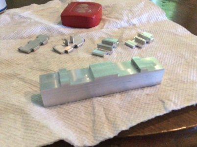
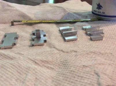
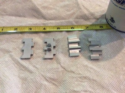
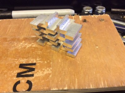
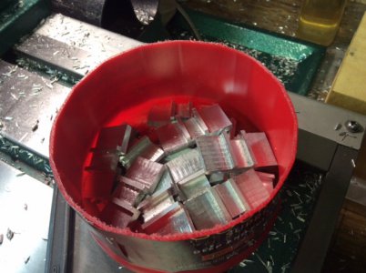
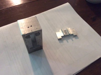
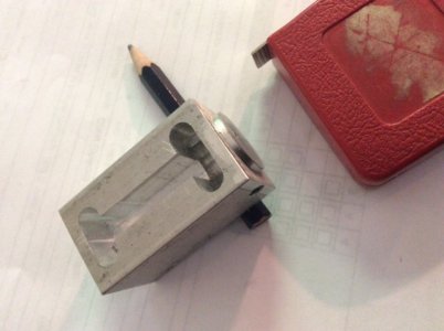
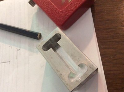
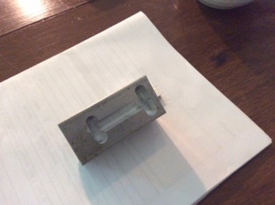
I am trying to make the track pads for a model crane undercarriage. What I have so far is pictured above. My question is how to proceed in a way to produce parts that are the same dimensions and will be sort of generic so that each pad will fit to any other pad. I started out with flat 1/8" thick bar stock and cut the sections to the rough length (or width actually). The pads are 1.5 x .5 and I am planning to use either piano wire or maybe brass rod to hinge them together. I have a few that are hinged as a prototype. What I found is I needed the cogs sticking up in the second from the left in order to drive the assembly. So, I decided to try using 1/4" thick stock and mill about the top half away leaving the slot down the center and eventually beveling the slot flanges so they will fold together as they round the wheels at each end. (Boy, this must be hard to follow...)

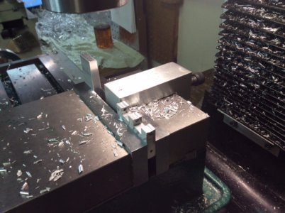
I also made a fixture block to hold a double stack of six each in the vice for milling. This seemed okay, but it seems like I still didn't get very repetitive results. I know this is all due to my inexperience.

But, when I decided to try the "three dimension" versions it seemed to complicate everything.

To simplify my question, would it be better/easier to mill the slot along 4 or 5 inches of the bar stock first, or, mill the overlapping fingers first, which would mean cutting the pads into individual pads first in order to make the finger notches on the leading and trailing edges of each pad?

I'm looking for any tips on what order or other ideas of how to produce the parts. I will need about 40 or so of these.

Thanks for looking, and if nothing else enjoy the pictures...


Jim
 
Make in batches, do all of the same cut for say...30-100 parts, then make the next cut and the next...it keeps your setups minimum. The only drawback is if you mess up one, you mess up the entire batch. Tim
 
Tim, that helps. I think I have been thinking that way but not actually doing it that way. Now that I have settled on a design I should be able to do as you suggest.

Jim
 
That looks really good,

The advice previous is good, some sort of set of jigs to hold each stage.

Good luck, make sure you post pics of the progress :)

Stuart
 
Progress! I made a bunch more of my newer style pads and DID batch them. This is working much better now. I also made a simple vise stop block which really helps. I think I made about 25 or so and then decided to "finish" 6 of them to make sure the design is going to work. So, the picture of the vise shows the drill guide that I was using for the version 1 pads, I need to widen the slot a bit. I will drill the six pads and bevel the drive dogs and then work on the drive roller. Once I prove all that, I can come back and make another 40 or so pads!

image.jpg image.jpg image.jpg
 
Nice work. I hope to follow in your footsteps some day.
Are you following the design of a particular crane? Also do you have a scale ratio?
The track pads on a P & H 1900 AL shovel are very similar to your design. If memory serves right the triangular portions are wider on each side of the pad and like your design fit into recesses on the propel tumbler.
I hope my work looks as good as yours when I get to that point.
Have a good day
Ray
 
Ray,

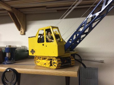
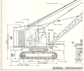
Thanks for the comment. I am making the undercarriage to fit under my NyLint truck crane. So, the scale is approximately 1:16. I am using some photos of plans/drawings of a Bucyrus 22-B that I found on the web. I could use more drawing so if you know where I could find some on the web that would help. In the first picture I have the crane sitting on an undercarriage from a diecast Oliver Dozer which looks a bit too small so I enlarge the photo plans until it looked about right.

image.jpg image.jpg
 
Track sections are typically made of twelve pieces per section: One pad, two rails (one left, one right), one pin, four bolts and four nuts. Photos should give you a better idea than any description I could give.

Rails and a chain, which is an assembly of rails and pins.

Track assembly, rolled up, but gives a better idea of the assembly

Welded track sections that someone came up with for a mini-dozer.

Track pins are normally a press fit in one end of the rails, but fit loosely in the other end. The exception is the master link, which has a loose fit on both ends. The pin that fits there is held in place by a cross bolt rather than being pressed in.

One other note on tracks: Cranes, excavators, and other tracked machines that only use the tracks for moving the machine from work place to work place usually use what is commonly known as a "street pad" which typically has three or four shallow grouser "teeth". This allows the machine to move across a paved surface without damaging the pavement. Many times cranes have no grousers on the pads at all, and use a smooth pad or shoe. Dozers and crawler tractors have only one large grouser per pad, so that they engage the ground better for pushing or pulling large loads that require brute force for movement.

I don't know if any of this helps or not, but thought I would offer what I could.
 
Terry,

That does help, I like the pictures. One thing I didn't realize until I started working on this was how different the drive sprocket is from a dozer compared to a crane. One using a sprocket like a gear and the crane using a drive cog like was shown the other day on the tracked snow thrower thread.

Jim
 
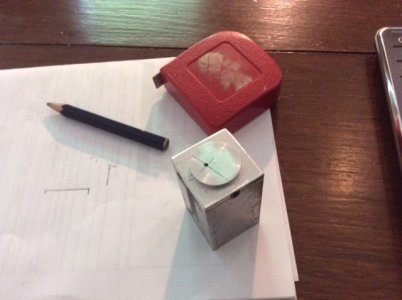
I was pulling my hair out trying to get a drill guide that positioned the hole in just the right spot. My lack of experience was really getting me I think? But, I think I finally came up with a good solution. I need to insert the track pads into a milled slot that holds the vertical and then I put the guide block with pad into my drill press vise and drill the hole. Well, I made about three of these and kept screwing up the hole location in the last step of making the guide. Here is my solution. I decided to bore out the top of the guide where I was trying to accurately locate the guide hole, and made a round bushing that drops into the hole and I hold it in place with a set screw. This let me make as many top bushings as needed until I got one I liked. I can also make one in steel if the aluminum proves too soft for the job.

image.jpg image.jpg image.jpg image.jpg image.jpg

Jim
 
Back
Top