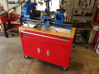
Craftsman / Atlas Lathe 101.07403 Ser 30948

OK well that motor did not work out for me.
I did buy a new motor.
Century Motor 1/2HP 1725rpm 115V 60Hertz 1ph 6.8amps J56 frame. Shaft diameter 5/8" and 1 3/4" usable length. Includes shaft key. This motor is selective rotation, clockwise or counter clockwise. Condition is "New".
The body of the motor is approximately 9" long and 6 1/4" diameter. The shaft extends 1 7/8" from the motor body.
I will look into the pulley from Clausing.


Thank you!
 
Anthony,

In the Machine Parts Wanted forum, you posted several photos, one of which is of the right end of the front way on the bed showing the serial number as being 30948, not 38948 as shown in the title of this current thread and also in one of your posts in this thread. Before I edit and correct the serial number in this thread title and in one of your posts therein, please confirm that both threads are about the same machine and that the machine is a 12x36 Craftsman Model 101.07403.
 
ALL,
So .... My Atlas/Craftsmen project is coming along. However I have a few assembly questions.
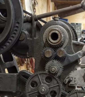
I assembled these gears to the best of my knowledge.
The big question is how is this lever installed? When I assemble the bracket the gears are too far away. I used another bracket on the opposite side to make it even. What am I missing? Im sure the bracket must go here.
Can anyone help?
Some of these parts came in a box Im just guessing.
Thanks
 

Attachments

  • 20210808_164605.jpg
    20210808_164605.jpg
    3.7 MB · Views: 36
  • 20210814_170330[1].jpg
    20210814_170330[1].jpg
    3.3 MB · Views: 30
  • 20210814_170348[1].jpg
    20210814_170348[1].jpg
    1.8 MB · Views: 31
  • 20210814_170708[1].jpg
    20210814_170708[1].jpg
    3.9 MB · Views: 30
  • 20210814_170437[1].jpg
    20210814_170437[1].jpg
    3.8 MB · Views: 33
What lever are you referring to, the L6-21 Tumbler? And too far away radially or axially?

And what bracket?

The Tumbler is in neutral in your third photo. The 24T Tumbler gear should be meshed with the 20T Tumbler gear and the 32T gear of the 32T/16T Compound gear and remain so in the other two Tumbler positions. The 32T Spindle gear should not mesh with anything. If you move the Tumbler to the upper detent hole, the 20T Tumbler gear should mesh with the 32T Spindle gear. If you move the Tumbler to the lower detent position, the 24T Tumbler Gear should mesh with the 32T Spindle gear.
 
Last edited:
I guess Im as clear as mud. As you can tell I know nothing about this Lathe. I am In the process of restoring it to full operation.
The gears I am referring to are the lower gear set that drives the lead screw. Does this assembly look correct? I believe the tumbler gear assembly is working correctly. Yes the tumbler is in Neutral in the third photo.
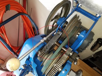
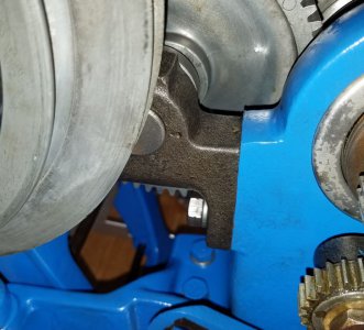
In photos 4 and 5. How is this the Lock L3-108 Assembled to the unit? I see where the rod L3-104 is attached to the countershaft assembly. It appears that the Lock L3-108 should be under the L4-245L bracket. Refer to Photo 5. As I mentioned if I assemble the Lock there the "back Gear" assembly is set back too far to engage with the headstock gears.
What am i missing?
Can someone show me how the Lock bracket is assembled? The item is circled in the photo ...
Thanks
 

Attachments

  • 20210814_170708.jpg
    20210814_170708.jpg
    3.5 MB · Views: 13
Last edited:
To take the L3-108 question first, yes, the L3-103 should be mounted between the flat on the headstock and the left back gear bracket. If putting it there puts the back gears and shaft at an angle ti the C/L of the spindle, my guess is that you have a 10-245L Bracket in that location instead of an L4-245L. The drawing of those parts in the parts manual was apparently always wrong in that it showed the L3-108 as having three holes through it but showed the L4-245L as only having two holes. Supposedly the L4-245L is about 3/16" shorter than the 10-245L and 10-245R and has two bolts and a pin in or through it. One bolt is either the same as the single bolt attaching the right bracket or a little shorter. The other bolt is supposedly 3" long. The pin is between the two bolts.

I am going to save this in case you come looking before I finish with the gear problem
OK well that explains it Those parts were in question to begin with. I purchased that whole back gear assembly and I assumed it was all correct. The assembly that came with it had a broken gear and that bracket was missing...... So in the meantime its not a show stopper. I will look for another. I see the difference.
Thank you so much for your knowledge and input.

Update ... I was able to source the correct part
So ... The next question is the part comes with shims. How do you set the gears with shims?? I not sure I understand.
 

Attachments

  • bracket.JPG
    bracket.JPG
    32.8 KB · Views: 15
  • bracket1.JPG
    bracket1.JPG
    77.8 KB · Views: 18
Last edited:
OK. I take it that the back gear sub-assembly turned out to have been off of a 10"? If you have the 3" long bolt and the L3-108 is present, the only part you are missing would be the L4-245L

On the gear meshing (or not) problem, which thread or feed are you trying to set up? There are combinations that you cannot set up. But none of them should be shown on the threading chart for the 101.07403.
 
As for the gears Meshing. I found more shims stuck between the fold in the box that the original lathe parts came in. The correct part that I ordered comes with shims as well. So you must need to add shims to those back gear brackets to set the depth of the teeth. Is there a spec to follow? How can I tell if the gears are set correctly?
Additionally ...
I think I have all of the gears spacers etc. for setting up the feed. See the stack of gears below. However the gears in place now on the machine are what was left over and they happen to fit as the parts page shows and as illustrated in my second photo above.
 

Attachments

  • 20210818_194441[1].jpg
    20210818_194441[1].jpg
    3.3 MB · Views: 21
Back
Top