Craftsman 12" Carriage Stop?

Well, I do have a few secrets, but am keeping quiet till 12/26! I looked at all the links and I think I can put something together from them. I also watched the "Toms" video and some others which made it look really easy. I'll post some pics when I get one pulled together.

Happy Christmas Gents! Without a doubt the friendliest, most helpful forum I take part in!!
 
Old daddy
On the 618 lathe group under calkins photos is a detailed drawing for a very basic stop you may like.
I am afraid to post pic of the drawing due to possible conflict of interest. He gives detailed measurements in the drawings.
Tomh
 
My simple carriage stop is two 3x 2 x 1/2 " thick aluminium plates , drilled and bolted into an " F" type vice with the pivot point a fraction greater than the lip of the bed
Once the centre bolt is tightened and the end bolt tensioned , it is rock solid and enough for my purposes as I always set the stop before hand to the exact point I want it to stop the hand fed carriage . For I'm not a fan of saying well it's nearly there and then having to concentrate on a micrometer at a finer setting .


As I have a simple digital " F " type micrometer that has a depth gauge so setting depths or distances from the work face is not a problem .
The main clamp top nut is a nylock nut and the bolt for it is thread locked into the tapped lower plate . The through hole in the top plate is 1'8 " greater than the centre bolt to allow it to move and not bind . The centre bolt is a high tensile bolt which means I can get a lot of clamping power on the stop
 
My simple carriage stop is two 3x 2 x 1/2 " thick aluminium plates , drilled and bolted into an " F" type vice with the pivot point a fraction greater than the lip of the bed

I'm having a hard time picturing it, Do you have a picture of it.

Bill
 
I copied/adapted the four stop stop above, my tiny Atlas/Clausing Mk@ doesn't have room for 4, but I managed to get three. Multibpe stop.jpg

The two square block have 1/4 20 screws inside, can be extended about 7/8 each.
 
I was wondering if anybody had an easy solution for a carriage stop? I've been using a small c-clamp, but it is a pain to set up and then rely on. I see them on Epay for $50 and more, which is a bit spendy. A good simple solution would be a great add to my tool kit. Thanks.

I have a South Bend 9A bench lathe. I bought a Fenner Drives Trantorque shaft mounting unit to use as a spindle stop or to temporarily mount other devices to the spindle opening at the change gear end. These devices are designed to securely mount things like pulleys and gears to shafts without needing key ways or set screws. The are like a collet and have a hex nut feature to allow tightening. They work great for synchronizing drives. The unit I have mates a 5/16" shaft to a 3/4" I.D hole. They have a reasonable adjustment range and are very concentric.

EDIT: Time for me to retire ! (Wait, I did that years ago). Somehow I transposed CARRIAGE into SPINDLE ! Silly Me. Oh well, this is still is a useful application for my lathe. Sorry guys
 
Last edited:
I have needed a carriage stop/position-er for a year (since I got this lathe).
Finding and posting all those links above, along with the immediate need to cut-off some parts to length inspired me.

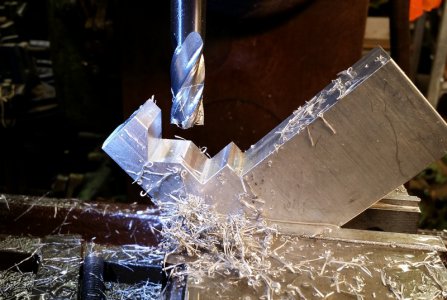
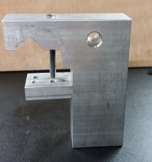
After some quick measurements and a sketch on the shop white-board I found an aluminum block and started cutting/milling.
I needed the dial-indicator mounted immediately, and just left room to add some kind of stop(s) later....
milling.jpg
body.jpg

I made two mistakes:
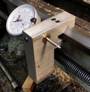
  1. I noticed that the indicator stem was not parallel to the ways; the hole for the dial indicator was not 90 degrees thru the block! Crap! I must have had some cuttings under it in the drill-press vice. I used the same 5/8" mill to make a new bigger hole that was square to the face, and made and pressed in a brass bushing. Rather than try to hide it, I'll show it off and claim it was design intent to add some flair, yeah that's it...
  2. I clamped the body and the clamp block together for drilling to ensure the holes were aligned. However, I had the clamp block on the wrong "step" of the body....oh well, spin the block around and re-drill/re-tap....no one will ever know! ;)
Here it is on the lathe:
installed.jpg

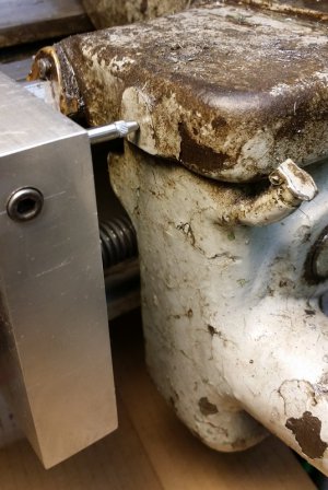
The dial indicator hits the target boss on the carriage nicely; and there is lots of room to add a couple stops in the future....
on_target.jpg

What would I change (other than the mistakes above), two things:
  1. Purely for looks I would put those two SHCS for the clamp block slightly further apart. They are on 1/3 body-width spacing, but due to the round holes they look closer together than they are to the edges. I think they would look better slightly further apart.
  2. I'd have done it a year ago!
Also I'd like to find a different dial indicator with at least a 2" travel.

-brino
 
Back
Top