Converting Dynasty Receptacle from 4-prong to 3-prong

My understanding is that NEC applies to wiring to the socket, beyond the socket (i.e plug/cordage it is UL). NEC does have specifications for color coding as you have noted and also specific to socket/plug ratings for different applications, but with UL you can get away with different color codes and smaller gauge wire then would be allowed under NEC.

That makes sense. However, I try to follow color schemes even when I wire plugs, just because it is easier to indicate which wires do what. I'm perplexed as to why you would not use the red wire over the white wire for the second LINE wire when it is available.
 
That makes sense. However, I try to follow color schemes even when I wire plugs, just because it is easier to indicate which wires do what. I'm perplexed as to why you would not use the red wire over the white wire for the second LINE wire when it is available.
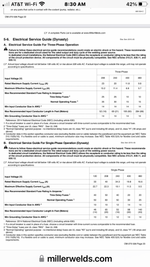
Most 4 wire cable like SOOW, SJOOW, etc. is black-red-white-green, specific 3 phase cable is typically 3 or 4 numbered black conductors plus a ground. Given that the Dynasty welder can run off of 120/240 single phase, it would make more sense to use the white conductor vs. red for L2/N. On the plug end the color coding is less relevant given that it is the plug configuration determines the voltage and amperage, the other end is hardwired at the machine.
 
That makes sense. However, I try to follow color schemes even when I wire plugs, just because it is easier to indicate which wires do what. I'm perplexed as to why you would not use the red wire over the white wire for the second LINE wire when it is available.
Same here. Even if it's not required, it just makes good sense to continue with the same color convention all the way to the end of the circuit. And I would never use a white wire as a hot, without marking it in some way( generally with the appropriate colored phase tape ). Everyone has their own personal pet peeves when it comes to such things. Heating up an unmarked white conductor is one of mine!:)
 
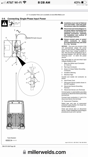
I had previous posted information on this in one of your previous threads on the question. The manual makes it clear that the welder can operate on voltages from 120-480VAC and single phase voltage or three phase voltage. So for three phase you would use black, white and red wires for L1, L2 and L3 respectively plus a ground. SIngle Phase is black and white fro L1 and L2 for 240VAC and would connect to N for 120VAC. The red wire is not used, for single phase and as indicated is taped off. The welder has an auto-sense and will configure the unit for the incoming voltage and phase w/o changing any jumpers. If I recall some people use and adapter jumper plug so they can used it in different settings/locations depending on the available power source.
View attachment 407605
I remember your response from early March of this year. I made that thread while my wife was doing the driving on a long road trip before the gas prices shot up. I have been working crazy long hours since I got back from that trip, and I did not make an effort to find my old thread.

In your response on this thread, you instructed how to wire it up for single phase. You said that the machine would autosense the voltage. So I should wire it up as below that for 220V?

Tape off (i.e. insulate and not use) the red wire coming from the machine, use the black and white wires (emanating from the Dynasty) as L1 and L2, and the remaining wire (which will be green, yellow or yellow/green) is the ground?

I’m going to post a better screenshot of the manual now. I will be attacking this task today.
 
Thank you so much to everybody for all of the help. I certainly would not want to smoke my Dynasty board.
 
Not wishing to take the post off topic, just curious if CEE form plugs and sockets are used much in the US ?

They might be known as IEC 60309

In the UK they are very popular in caravan holiday parks, boat marinas , workshops, live performance venues due to there robustness , availability in a range of amps, pin & voltage options, also weather resistant.


(blue ones 240v)

Stu
 
The plug/cord needs to be UL compliant so IEC connections are not used in the US. It also gets a bit more complicated as to rating for plugs/sockets depending on the application, so when used for motors and as a power disconnect, it does not go by the amp rating of the plug/socket (socket/plugs have specific Hp ratings). Erik, you always would want to use 240VAC over 120VAC in these types of applications, and in some cases 3 phase over single phase. My understanding is the Dynasty welder auto-senses the voltage/phase so the available welding power/duty cycle is adjusted accordingly. The plug you purchased is specifically for 240VAC 50A, so that is how it should be wired. The socket needs to wired according to NEC, typically wires going from the socket to the breaker, L1 would be black and L2 would be red, plus a green ground, and a 50A circuit is typically #6 for copper wire. You may find extension cords for welders that use #8 because they fall under the UL specifications.

Sockets/breakers in most applications are rated for 80% continuous duty of the rated amperage, so a 50A would be rated for 40A continuous duty under NEC. This is the reason why things like toaster ovens, motors, etc. that plug into a standard 15/20A 120VAC socket are usually limited to around 1600W or a 1.5 Hp motors.
 
Success!

I will tell the story. My Dad was born in 1942, and, despite seeing the manual recommending taping off the red wire, he was adamant about taping off the white wire. Of course, I am talking about the wires coming from the Dynasty.

Him and I carefully looked over this thread together. It was pretty clear to me that taping off either the red or the white would work.

Long story short, Pops was *unwilling* to tape off the red wire. Had I insisted on following the manual verbatim (i.e. taping off the red wire), he was ready to walk out. His argument was that, doing it his way, you had 220V going between the black and red wires.

We had made a diagram of what wires were coming from the panel into my receptacle box. As you can guess, there was green for ground, and black and red wires which were both hot.

Looking at the 3-phase wiring diagram that Mark had posted, I could see that the black, white and red were L1, L2 and L3 respectively. It was at this point that I decided to follow my Dad’s recommendation and tape off the white (L2!) wire.

So that’s what we did, and it tested A-OK. I *really* appreciate everybody’s help! You guys saved me from having to buy an expensive Miller adapter that I cannot imagine being able to afford.
 
Back
Top