Compound Delete

So you disengage the gear chain (train?) and move the Z-axis slightly between each threading pass to simulate feeding the tool it at 30 degrees? Then re-engage the gear train for the next pass. I must be misunderstanding as this doesn't make any sense.
Doing it that way requires that both x and z have to be advanced. It's basic trigonometry.
 
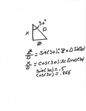
I made a drawing to help explain what I'm talking about.

NoCompoundThreading.jpg
The drawing shows the compound set over by 30 degrees. If the compound is advanced by distance "D", the cutter advances a distance Z given by D*sin(30) and X is given by D*cos(30). If instead we advance Z and X by those amounts (leaving the compound alone), the cutter ends up in the SAME location. The cutting tool and the work don't know how it got there, the motions are exactly equivalent.

The amount we advance X looks a little unhandy so this method is best done if you create a spreadsheet to calculate X, or if you have DROs on both X and Z you can reset X after each pass and use the same distance over & over again. I prefer the spreadsheet method because you get a direct readout of the thread depth, shown on the X axis.
 
I understand how moving X and Z produces a path along the 30 degree line but not understanding how you disengage and re-engage the gear train driving the Z-axis leadscrew. You disengage the change gears, rotate the screw to move the Z-axis the required amount, then re-engage? That would seem to put the Z-axis right back where you started assuming you engage the same teeth in the drive train. I'm obviously missing something here.
 
Not that it matters, but I’m with npalen, in not understanding. If the compound is absent, no amount of moving the carriage will recreate the angular travel offered by the compound. It seems to me, simple mechanics winning over the simple trig. Leadscrew to carriage interface is more or less fixed by the leadscrew pitch. The relationship of cutting tip to carriage position is fixed about a center. But as long as it works for you, have at it. I’ll still be using dies. Lol
 
As far as I'm aware opinions and options have been aired and everyone has retired to their corners. What more needs to be said?

Proceed with the approach that best suits you and you probably will be satisfied with the results.
 
We are asking for you to explain how you disengage the drive train between the leadscrew and the spindle, make an adjustment in the Z-axis position and then re-engage the drive train without nullifying the adjustment.
 
I don't generally do that much heavy hogging so rigidity isn't a huge need.
Not that my old lathe can't carve off some metal - a .250 doc in 1018 wouldn't make it break a sweat.
But how often does one try to turn to a precise diameter at that rate of metal removal?
I don't think I ever have. I learned to do the heavy removal, then back off on on the doc and feed, increase speed, maybe change the insert or cutting tool and sneak up on the desired diameter more gently.
And if I was trying to cut a very precise diameter I might even set the compound at 45 degrees so that turning in the compound dial 001 would decrease the doc to .0005 or even set it at 30 degrees to reduce it to a third = .00033.
But more likely I would do as I always do which is to grab a file and/or some emery cloth and bring it to spec that way.
As for threading, I flunked trig and became an English major.
But I can still set the compound to 29.5 degrees, do the simple math (750/N) and cut an external ANS thread that works - most of the time....
 
I'm not understanding the question.
This may not apply at all to what you are asking but here goes. If you are cutting imperial threads on a lathe with an imperial lead screw, When the threading pass has reached the end of needed travel, you disengage the halfnuts, using the carriage handwheel or the powerfeed and return to the start point. With the lathe running in the required direction, start the feed by engaging the halfnut lever when the dial passes the same point you have chosen to use in the first pass. (Depending on what thread you are cutting there can be multiple dial #s that will work.) As the threading dial approaches the desired #, just before it gets to the #, put just a little pressure on the lever so that as the # comes up you can just push the lever down and engage without needing to slam it down like I sometimes see.

Now to the issue of having a lathe that has an imperial lead screw and needing to cut metric threads. Or vise versa. (There are lathes that have gear boxes that can cut both types of threads using the above method, but not common on lathes most people have.) You need to keep the half nuts engaged once you start. This means after completing a threading pass you stop the lathe back the cutter out, reverse the spindle rotation, back to the beginning of the cut. Stop the machine, move the cutter in a bit deeper than the last cut, change the rotational direction of the spindle and start the feed again. It is much easier to do all this if you can feed from the shoulder or the part out to the open end. No need to try and stop suddenly as you approach the shoulder. Watch Joe Pie's videos on threading. Much easier to see than me trying to talk about it. He simplifies the entire procedure. There are those on this site that don't like his method for reasons I've been unable to understand, but to each their own. I subscribe to the KISS principle.

Was this an answer to what you were asking? I should have just said WATCH JOE PIE'S videos! The guy is very good.
 
The question is how, using a combination of X-axis and Z-axis adjustments between threading passes, can the +-30 degree setting of a compound be simulated.
The answer is: Its impossible on a conventional lathe even with a leadscrew handwheel and DRO fitted to the Z-axis. The half-nut has to engage at predetermined position(s) relative to the spindle rotation.

Adjusting the X and Y axes as described by homebrewed in post 22 above will not work to simulate a compound set at +-30 degrees.
 
Back
Top