CNC PM-728V-T

AFAIK, the centroid Oak and Acorn require use of their CNC12 software and are not compatible with Mach 4.

The Oak serves a different customer base than the Acorn. Make sure you need the features it has rather than getting it because it is a "better" board. The Oak is meant for you to use their drives with AC or DC servos. It is not appropriate for steppers, Clearpath servos, or servos with standalone drives.
Yes, I have looked into the Oak because it is a true closed loop system. It can support more than 4 axis. Also the Acorn only supports one encoder input. Regardless of what controller I upgrade to, I am definitely going to be upgrading motors in the future.

I used the G540 because I already had it and was going to upgrade to mach4 to reuse it on a plasma table build. I am going to use the centroid on a lathe conversion so I might as well get familiar with their CNC12 software.

I have plans to lease some industrial space once the current occupant retires in the next couple years. Then I will be able to purchase larger machines. I bought the pm-728vt because it was easy to move into the basement. I want to learn more than just stepper motors and have a better understanding of a more industrial type controller and setup. Yes the Oak would be overkill for the 728 but it would be a learning experience for me.

I’m thankful for communities in forums like this and others. Without them I probably wouldn’t attempt to take on projects.

Thanks for the advice and input from everyone :)
 
Last edited:
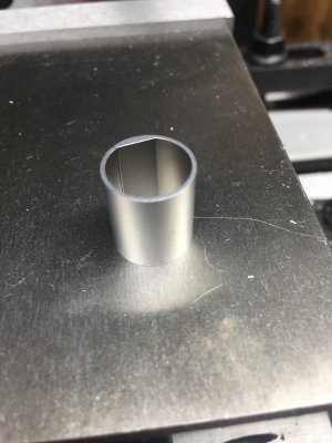
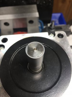
Made an adapter to use 1/2” shaft stepper with 14mm ID coupler. It collapsed a little but fits nice. Will check it for runout once I solder the cable to the stepper.

Probably going to install the ballscrew and motor for the z axis today.
 

Attachments

  • 3BCD3129-65CB-4278-9F32-5DBB61E09AB7.jpeg
    3BCD3129-65CB-4278-9F32-5DBB61E09AB7.jpeg
    854.1 KB · Views: 199
  • B1E848A7-1040-4F72-A93C-C2B1BB6DC3B8.jpeg
    B1E848A7-1040-4F72-A93C-C2B1BB6DC3B8.jpeg
    812.7 KB · Views: 205
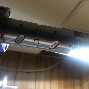
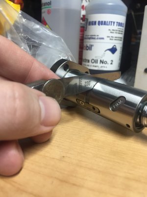
I decided to take a closer look at the Z axis double ball nut before installing and noticed that there is a gap between the spacer.

The gap of light that is in the first pic is at the bottom left side of the spacer.

Has anyone else noticed this?
 

Attachments

  • 593C7F0A-CBA8-4094-8A9E-DF0503219B48.jpeg
    593C7F0A-CBA8-4094-8A9E-DF0503219B48.jpeg
    465.5 KB · Views: 204
  • CCFE8A59-127B-476E-AAF4-7FD76DA5F9EC.jpeg
    CCFE8A59-127B-476E-AAF4-7FD76DA5F9EC.jpeg
    690.5 KB · Views: 195
I decided to take a closer look at the Z axis double ball nut before installing and noticed that there is a gap between the spacer.

The gap of light that is in the first pic is at the bottom left side of the spacer.

Has anyone else noticed this?

That is no good. You have zero preload on the ballnut and therefore the double nut is doing absolutely nothing more than a single nut.

Making a new spacer is trivial on a surface grinder, but a bit trickier on a lathe. A tenth or two of difference in height makes a big difference in the preload. Also the faces must be very parallel or you will tip the nuts relative to the screw.
That’s what I was thinking but wasn’t sure. I sent some picks of it to PM just a little bit ago.

I researched a little bit about shimming the ballnuts. The faces being parallel was definitely something that was emphasized. Worst case scenario, do you think it would be possible to wire edm the ID and OD, then slice it off and lap off the cutoff tang and then split it in half. ( I have way more axis to edm rather than a lathe or surface grinder

I did come across someone working on a larger machine and was able to loosen the key that locks them and tighten the ballnuts snug to the spacer. This gave him desirable results... one thing I noticed is the key only had one Philips head screw in it as you can see in the pic

Sure you could do that. The ID and OD are not particularly precision, so why not buy some steel tubing and use the EDM to finish the flat faces?

The key should keep the ballnuts from rotating relative to eachother. I would definitely expect to see two screws holding it together. The spacer thickness should be such that when the ballnuts are clocked to eachother such that the key fits in the slot, the spacer is firm against both faces and under a few tenths of preload. This is probably a trial and error deal to get it right.
 
Made an adapter to use 1/2” shaft stepper with 14mm ID coupler. It collapsed a little but fits nice. Will check it for runout once I solder the cable to the stepper.

Probably going to install the ballscrew and motor for the z axis today.

I'm intrigued... How did you machine the internal D?

EDIT: Forgot you said you had EDM equipment, that is sweet. That would would be a complete headache for me to make with the equipment I have. Maybe on the CNC, but it wouldn't look that sharp.
 
Why would you not just return that?
Robert
I contacted PM about it and sent some pictures. They responded quickly as usual but have not said anything other than they will be looking into it since it’s a fairly new product.

If it can be tightened up more against the spacer I’ll just do that. But waiting to see what the have to PM has to say about a resolution before I touch it.
 
Sure you could do that. The ID and OD are not particularly precision, so why not buy some steel tubing and use the EDM to finish the flat faces?

The key should keep the ballnuts from rotating relative to eachother. I would definitely expect to see two screws holding it together. The spacer thickness should be such that when the ballnuts are clocked to eachother such that the key fits in the slot, the spacer is firm against both faces and under a few tenths of preload. This is probably a trial and error deal to get it right.
Yes tubing would be easier. I was mainly thinking about slicing the thickness and then cutting the ring in half. Just use a rough single pass to make the OD and ID since I have flat stock on hand

I was confused that there is only one screw in the key and it appears the opposite hole that doesn’t have a screw in it, and is threaded? Yet there is no hole or threads on the second half of the ball nut?You can it if you zoom in on the pic with the shim.

That’s why I was hesitant to try and tighten it up onto the spacer... I’ll wait to see what PM says about this. But I feel like I’m going to be pulling X and Y back out too.
 
Back
Top