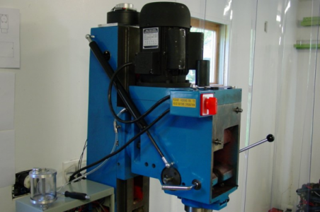
CNC Mill Motor replacement

I have an extra thought for your consideration, since you are replacing so much...... I long for the ability to do rigid tapping however, because the VFD - motor combination is not that precise (can be off several percent) with respect to the speed (open loop) and cannot reverse quickly (spin up and spin down delays) it does not seem to be the route to go. I think my VFD could take a speed sensor input to control the speed, but I have not investigated this as there is no easy access point on the spindle to attach a tachometer. If I were rebuilding all of your spindle drive I might want to add this feature via DC servo or stepper for the spindle motor. Yes, much more expensive. Also, my spline plus gear box have quite a bit (a couple of degrees) of backlash in them.

By the way, another consideration you may not have thought about is the weight. If you get two much weight on top, the stepper may not hold the z-axis when the power is shut off.... hence your tooling may crash into your work or table! I have observed this on my machine.

I have a (Precision Mathews) PM-940M CNC mill with a 1.5KW 3ph motor being driven by a Delta VFD. With the Mach3 software the mill was was set up for the spindle seems to run fine (it also has a poorly documented nMotion controller for the steppers, but this is separate from the spindle).

You can look up the details of the motor and VFD manual on line:
Delta Model VFD015E21. Tag says: Input: 1ph, 220-240V, 50/60Hz, 15.7A; Output: 3ph, 0-240V, 7.5A, 1-599Hz.
A quick look indicated that this model VFD is around $500, but you maybe able to find it cheaper. There is a front page photo and manual at: http://www.altonji.net/up/uploads/VFD-E.pdf Mind looks like the one on the left in the photo.
My motor looks similar in shape to the spindle motor in your photo, but maybe larger. Air cooled with a fan on top.

However, I long for the ability to do rigid tapping and and because the VFD - motor combination is not that precise on it speed (open loop) and cannot reverse quickly (spin up and spin down delays) it does not seem the route to go. I think the VFD could take a speed sensor input to control the speed, but I have not investigated this as there is no easy access point on the spindle to attach a tachometer. If I were rebuilding all of your spindle drive I might want to add this feature via DC servo or stepper for the spindle motor. Yes, much more expensive. Also, my spline plus gear box have quite a bit (a couple of degrees) of backlash in them.

By the way, I have a spare 3 phase 1.5KW Motor if you are interested. It is brand new and still in the box. You would need the VFD to convert from single phase 220 V power. It is heavy, ~40#.
 
Hi thanks for the offer, I already purchased that ebay motor and vfd. I think the struts on the z axis should handle to bigger motor weight. Ive had to remove those struts before and they probably push 75-100 # each, so fingers crossed.
 
Hi,
No problem. I have some other places I may use that motor.
However, your reply about the struts do not seem to be what I was addressing. In fact, I am not for sure what you mean by struts, but I will assume that this is the vertical support column containing the ways for the head stock ways to run on.

On my PM-940M CNC that I purchased I find that, on occasion, when powered down the head will actually fall...slowly until the tool hits the work or the table! Worst that even this is that sometimes up going steps are lost! I weight the assembled head stock by cranking it down until it rested on a scales. It is between 230 and 270 # plus tooling. In thinking about it, it is effectively suspended by the stepper motor cogging and way friction. If you take the stepper loose the weight causes the z-axis lead screw to unwind as the head falls. When the power goes off the only thing that holds the z-axis is the cogging of the stepper motor and friction. The crashing of the tool into the work or table is one problem, but also the vertical height is lost in the drive software. (I have experience both of these.) I am guessing but it appears that the weight of the head is sufficent cause the head weight to rock a little on the vertical ways... slightly. This rocking then interacts with the z-axis lead screw and I suspect causes it to flex slightly where the head stock lead screw nut (recirculating bearings) is attached. This flexing appears to be sufficient to move the stepper abit and so it uncogs and drops one cog's worth of distance. This seems to almost resonate and the process rapidly repeats itself resulting in the stepper turning and the lead screw unwinding to lower the head stock. I have found this to be dependent upon the veritical location of the head stock. When near the ends of the lead screw it is not as sever a problem. Perhaps there is less lead screw flexing.

So for me there are only three possible solutions that I have found or have conceived of: 1) Tighten the ways up until the flexing is eliminated, but the friction is much higher. Too much friction and surely wear increases and it is not clear that the stepper can over come this plus the head stock weight. Also, it is not clear that this does not work itself loose again. 2) Buy a much bigger stepper motor (and drive) for the z-axis so that the cogging is stronger. (All three steppers on the 940M CNC are a bit on the small size and the drivers supplied will not push any more current.) 3) Build a counter balance for the head stock. My concept is to put a pulley on top of the vertical support and a cable from the head stock over the pulley and back down the back of the mill to a counter weight. I am thinking of doing this, but it will effectively double the weight on the vertical support column and the mass of the head stock will double meaning that start up and stop acceleration is slower. Of course gravity is working on the counter balance and head stock weight and so one must compare the acceleration of the gravity vs. that from the stepper. Another approach to the counter balance would be to use a spring (torsion spring like on a garage door.

Anyway, I wish you luck and look forward to hearing how you come out.
 
You mentioned in your first post that you were looking at bypassing the gearbox. I would recommend that you do this as most gear systems are designed to work at the maximum rpm as delivered from the factory. Not to mention that the gear noise would be amplified at higher RPM's. On the plus side removing the gears would help counteract the head drifting down as described by B2 in his post above.
 
How is the motor replacement coming? I looked at the VFD and couldn't find a make/model. You may already be aware of this but if it's a Huanyang there are Mach and UCCNC plugins that allow you to control it very easily via gcode with 2 wires and a cheap RS485/USB adapter (about $5 on amazon or ebay). If not your VFD may have MOBUS which will also allow control. I use the HY plugin on a 2.2kw spindle/HY VFD for a CNC router and it works great.
 
Hi,

However, your reply about the struts do not seem to be what I was addressing. In fact, I am not for sure what you mean by struts, but I will assume that this is the vertical support column containing the ways for the head stock ways to run on.

I believe the "struts" mentioned were gas springs. These are used in place of a counterweight system to balance the head & motor assembly. Generally two struts are used (one on either side of the head); one end is attached to the head and another is attached to the base or column. The struts are specified so that - hopefully - the weight of the head is essentially neutralized by the strut force. The Z-axis motor is now getting a boost from the spring force and upon powering down the head doesn't fall.

Upside is less mass to acelerate than with a counterwight system. Downside is that the struts can get expensive compared to a pulley and concrete block, and it's difficult to find some configurations (certain body to stroke lengths).

Below is one installation (internet photo). Mine are attached to the base and head.


1543699690520.png

As for rigid tapping with an induction motor and VFD - it's all dependent on the control software. If your controller supports it it's easy to implement, regardless of whether you're running open loop or closed loop to the VFD. You just install an encoder with an index signal or trigger on the spindle, and send the encoder signals to the control software.

1. Controller is programmed with the PPR of the encoder.
2. A rigid tap cycle is commanded and the controller tells the VFD to start spinning.
3. VFD spind the motor at commanded speed, and the controller is monitoring the encoder A/B and index signals.
4. When the index signal is triggered the controller moves the Z-axis to follow the spindle - they are electronically geared together.
5. Once the Z-axis has reached the lowest programmed point, the controller signals the VFD to stop and reverse.
6. Controller sees the encoder change direction and again it commands the Z-axis to follow the spindle up at a step rate that is appropriate for the thread pitch and the actual spindle RPM at any given moment.

Likelyhood of success is diminished with any Z-axis backlash or lost motion. Too coarse of an encoder will also cause problems - but too high a PPR may overwhelm the BOB and/or controller at higher speeds. Depends on the BOB optos.

You don't even need a rigid spindle to motor belt drive since the encoder is directly on the spindle. If you use an off-set encoder driven by a belt, then you'd need a zero-backlash drive system, of course.

-Ralph
 
Its been a while (I was away travelling in Costa Rica =D) but the motor and VFD both arrived in December. I wired them up temporarily today just to make sure they actually work and indeed everything works fine.

Im busy with a bunch of higher priority stuff right now so its going to be another month before I attempt to pull the gears out of the mill head. I think the motor I bought might just be too big though - maybe the weight wont be an issue but I dont think its diameter will clear the spindle top (where the draw bar comes out).

Anyway once I make some progress Ill post more pictures.
 
Back
Top