CNC AC Power Circuit Questions

FWIW my stepper motors and drivers are the same as what Steve used in his mill conversion. Maybe he can clarify if the motors are enabled at startup as I wouldn't now how to determine that.

On my mill I did use the enable circuit, so if mach3 is running and not in e-stop the motors are braking. If mach3 is not running and the controller power is on the motors are not braking. My controllers have a half power at idle setting, if I remember correctly, so they wont heat up at idle.
Steve
 
On my mill I did use the enable circuit, so if mach3 is running and not in e-stop the motors are braking. If mach3 is not running and the controller power is on the motors are not braking. My controllers have a half power at idle setting, if I remember correctly, so they wont heat up at idle.
Steve

Steve,

Thanks for the clarification. I'm slowly working my way through wiring this thing up. Hasn't been as hard as I thought but still have a few hurdles to get over.

Tom S
 
On my mill I did use the enable circuit, so if mach3 is running and not in e-stop the motors are braking. If mach3 is not running and the controller power is on the motors are not braking. My controllers have a half power at idle setting, if I remember correctly, so they wont heat up at idle.
Steve
Steve,

Thanks for the clarification. I'm slowly working my way through wiring this thing up. Hasn't been as hard as I thought but still have a few hurdles to get over.

Tom S
 
Steve,

Thanks for the clarification. I'm slowly working my way through wiring this thing up. Hasn't been as hard as I thought but still have a few hurdles to get over.

Tom S
The coil terminals on the contactors should be labeled A1 and A2. It is common practice to connect the 24V common (0 volt, blue wire in this case) to A2. In an AC circuit, the polarity doesn't matter. If it were a DC circuit the A1 would normally be marked +, and A2 would be marked -, these marking may be on the contactors even though they have AC coils.

I'm not exactly sure if I answered your question, but it's late.
.
.

It worked!!! Thank you Jim. Connected the input power to the transformer and ran a wire from the 24V common to A2. Another hurdle down. A1 was already wired through the power switch and E-stop. The spindle runs in reverse. Unrelated to the transformer/contactor issue but I'll tackle that later.

Started wiring the relay and power supply circuit and the fans. After that it's the control wiring.

Tom S
 
The fuse should be located imediatly after the mains input connector, if its hard wired to a distribution panel and the cable size is the same as the cable feading it you don't need a fuse, the cable probably gets smaller from the contactors, so as their is a cable size change to a smaller size that would want to be fused. E.g. Big cable comes in covered by big fuse, splits into multiple smaller feeds to psu's each psu feed gets a fuse.

What do the contactors do ? In the drawing it looks like you have no way to turn them off? (Sorry if thats a silly question). Ow i think I just saw the season for the contactors in a reply, I would personaly go with a big switch unless you wish to be able to power it up and down from software.

Stuart
 
Last edited:
The fuse should be located imediatly after the mains input connector, if its hard wired to a distribution panel and the cable size is the same as the cable feading it you don't need a fuse, the cable probably gets smaller from the contactors, so as their is a cable size change to a smaller size that would want to be fused. E.g. Big cable comes in covered by big fuse, splits into multiple smaller feeds to psu's each psu feed gets a fuse.

What do the contactors do ? In the drawing it looks like you have no way to turn them off? (Sorry if thats a silly question). Ow i think I just saw the season for the contactors in a reply, I would personaly go with a big switch unless you wish to be able to power it up and down from software.

Stuart

I have two 15A breakers that I plan to wire between the main power input and the terminal block feeding the power supplies and fans (one 220v 30A circuit in then split into 2 15A feeder circuits). The power supplies are 110/220 volt capable. I'll have to run a 110V circuit for the fans. Fuses will be in between the terminal block and the individual devices. Does this make sense?

I'd like to power everything with 110v but the one circuit I have available is nearly maxed out with the equipment I have now. Eventually I plan to add a 4th axis power supply and a coolant pump and who knows what else. My options are to run another 110v circuit or use the 220 I have available at the mill. I'm open to suggestions from the more experienced electrical people on this site.

The original spindle contactor power on switch, power off switch and e-stop wiring is still in place. This circuit works as it came from the factory. I'll post some pictures of the AC wiring layout later today so you can see what I've done.

The power supplies are 110/220 capable. The X and Y axis supplies have a 110/220 selector switch. The Z axis has a DQ2722M power supply/driver but no input voltage selector switch. My question is: how do you adjust for 110v vs. 220v input voltage? Does it adjust automatically? Is it a dip switch setting? I searched on-line but couldn't find an answer.

Thanks,


Tom S
 
The X and Y axis supplies have a 110/220 selector switch. The Z axis has a DQ2722M power supply/driver but no input voltage selector switch.

That power supply automatically senses the voltage. Just like most modern computer power supplies. I am using the same drive on my press project.
 
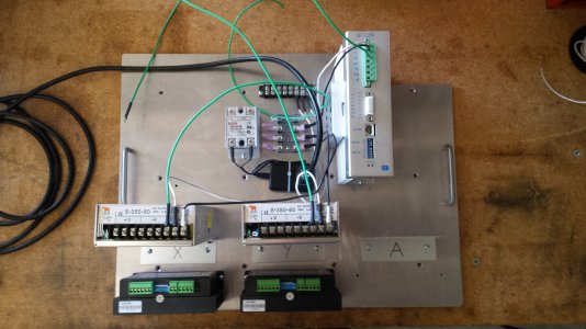
Here are a few pictures of what I've done so far on the wiring.

The first picture shows the X and Y axis power supplies and drivers and the Z axis power supply/driver combo unit. I've roughed in the AC power to the power supplies and DC transformer. The open space in the upper left hand corner is where the breakout board will go. Also left room for an A axis PS and driver.
20150301_083943.jpg

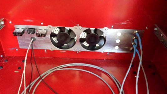
This picture is of the rear panel showing the layout of the two 15A breakers, 110V receptacle, the fans and the X, Y and Z motor plugs and wiring. The three open holes are for the limit switch aviation plugs.
20150301_084021.jpg

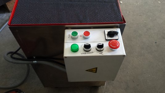
I relocated the power panel from the mill head to my rollaway that has the electrical and electronics in the bottom drawer. I'm going to put a monitor and laptop on top. I've got excess flexible conduit so I can move the rollaway about 7 or 8 feet away from the mill so I don't have to worry about chips and coolant fouling the computer.
20150301_084040.jpg

Still have quite a lot to do bit I am making progress.

Thanks for looking.

Tom S
 
Back
Top