CNC AC Power Circuit Questions

TomS

Active User
H-M Supporter Gold Member
Joined
May 20, 2013
Messages
1,906
I'm working on my CNC conversion and am at the point where I can wire the AC power circuit. I don't have much electrical smarts so I've done quite a bit of web surfing and reading the posts on this forum to learn as much as I can. I'm still trying to figure out some of the details.

I've drawn a circuit diagram (below) to help me explain what I've got in mind for the specific reason of getting feedback from the experts on this site. Comments and criticism are welcome. For clarification the AC input will be switched. Didn't show the switch and a few other details to keep the drawing simple such as a fuse block. Didn't shw the fuse block because I'm not sure where it should go. I'm thinking it should be wired in the line side of the circuit between the relay and power supply. And speaking of fuses what fuse rating should I use? Two of the power supplies are rated at 6A and one is rated at 7A.

Thanks for your help.

Tom S
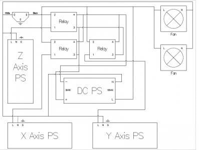
AC Circuit.jpg
 
Few questions and comments

1) When you say 6A and 7A, is that on the AC input side? If that is on the AC side, you will be pretty close the max capacity of a 120V circuit (25A typical)
2) What is the reason for 3 separate relays?
3) I don't understand the reason for the DC PS feeding into the relays for the X/Y axis power supply. If I understand the arrangement, as soon as the AC power is switched on, the DC supply will come on, actuate the relays, and then the other power supplies. The only advantage I could see to this is to stagger the startup, but the power supplies should not pull much current without a load connected.

I would consider changing the arrangement as follows

1) replace the 3 relays with a single relay, feeding all 3 axis supplies.
2) Have the DC PS connected directly to turn on the fans.
3) Connect the relay input to your CNC controller through a physical EStop button like this one

http://www.automation4less.com/store/proddetail.asp?prod=2ALMPP4LB-024

So that you can cut power to the machine axes if things go pear shaped.

As for the fuse, I would put it between the AC input and everything else. Add it on the line side (hot). Make sure you have a nice solid ground coming in, and if the enclosure you are using is metal, make sure you secure that ground solidly to the enclosure at a clean metal surface (scrape off some paint if you need to).
 
Few questions and comments

1) When you say 6A and 7A, is that on the AC input side? Yes. If that is on the AC side, you will be pretty close the max capacity of a 120V circuit (25A typical) I agree. Do I need to have more than one 120V circuit feeding this equipment?
2) What is the reason for 3 separate relays? I was following jumps4 CNC build. I'm probably wrong but my understanding of his build was that's what he did.
3) I don't understand the reason for the DC PS feeding into the relays for the X/Y axis power supply. If I understand the arrangement, as soon as the AC power is switched on, the DC supply will come on, actuate the relays, and then the other power supplies. The only advantage I could see to this is to stagger the startup, but the power supplies should not pull much current without a load connected. I may be wrong here but I'm thinking that when power is turned on the motors are at their max holding torque thus drawing maximum amps. Isn't this too much current for the on/off switch to carry?

I would consider changing the arrangement as follows

1) replace the 3 relays with a single relay, feeding all 3 axis supplies. Each relay is rated at 40A so this should work.
2) Have the DC PS connected directly to turn on the fans. The fans are 120V.
3) Connect the relay input to your CNC controller through a physical EStop button like this one

http://www.automation4less.com/store/proddetail.asp?prod=2ALMPP4LB-024

So that you can cut power to the machine axes if things go pear shaped. Yes, that is my plan.

As for the fuse, I would put it between the AC input and everything else. Add it on the line side (hot). Make sure you have a nice solid ground coming in, and if the enclosure you are using is metal, make sure you secure that ground solidly to the enclosure at a clean metal surface (scrape off some paint if you need to). I have two 15A breakers available on the inlet panel. I could use one to feed the X and Y power supplies and the other to feed the Z axis, the DC power supply and the fans then have individual fuses to each. Would this work?

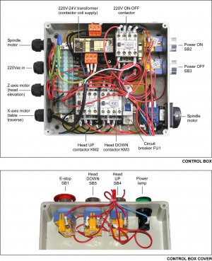
Here's a picture of my control panel. I've stripped out the KM2 and KM3 contactors and their associated wiring and switches. My plan is to feed the AC circuit in my AC circuit drawing above by tapping into a 120V lead off of KM1. All other circuitry will remain such as power on/off, spindle on/off and forward/reverse, and emergency stop. What do you think of this?

Thanks for your questions and input. I don't have any electrical experience and need all the help I can get.

Tom S.
Controls Wiring.jpg
 
Just a note I found out by accident
the e-stop turning off the ac to the power supplies may not stop machine motion instantly.
dc power supplies have capacitors in them that take some time to discharge and motion can continue for what seems a long time when things are going very wrong. The e-stop that i found that works the fastest is to an input pin to the pc. It stops sending pulse and motion commands so all motion stops.
I don't know what controller software you are going to use, but stopping the program stops the machine the fastest.
I entered a bad line of code when I first built my machine and hit the ac power switch on my controller to stop it, to my amazement the machine just kept moving until the power was depleted.
Steve
 
  • Like
Reactions: DMS
I'm guessing the box you show is part of the existing mill? Steve's comment about not stopping when AC is cut is a good one.

I guess whether the motors are on at full torque on startup depends on the type of motor, and the type of driver. With my motors and drivers, they are dissabled until I enable them, so startup current is nearly 0.

I might also suggest that if you have not selected your axis power supplies, then finding some 220v input supplies would reduce the amount of current you need.

Overall, I think you are on the right track. Keep us posted.
 
Just a note I found out by accident
the e-stop turning off the ac to the power supplies may not stop machine motion instantly.
dc power supplies have capacitors in them that take some time to discharge and motion can continue for what seems a long time when things are going very wrong. The e-stop that i found that works the fastest is to an input pin to the pc. It stops sending pulse and motion commands so all motion stops.
I don't know what controller software you are going to use, but stopping the program stops the machine the fastest.
I entered a bad line of code when I first built my machine and hit the ac power switch on my controller to stop it, to my amazement the machine just kept moving until the power was depleted.
Steve

Thanks Steve. This is the type of information that comes from experience, which I don't have.

Tom S
 
I'm guessing the box you show is part of the existing mill? Steve's comment about not stopping when AC is cut is a good one.

I guess whether the motors are on at full torque on startup depends on the type of motor, and the type of driver. With my motors and drivers, they are dissabled until I enable them, so startup current is nearly 0.

I might also suggest that if you have not selected your axis power supplies, then finding some 220v input supplies would reduce the amount of current you need.

Overall, I think you are on the right track. Keep us posted.

Yes, the box shown is the existing control box.

FWIW my stepper motors and drivers are the same as what Steve used in his mill conversion. Maybe he can clarify if the motors are enabled at startup as I wouldn't now how to determine that.

I did some searching and found that my power supplies are 110V/220V capable. I had assumed they were 110V only.

I have another thread going on the Precision Mathews forum showing my CNC conversion. Here's the link. http://www.hobby-machinist.com/threads/taking-the-cnc-plunge.24858/

Thanks again for responding.

Tom S
 
Bear with me as I know just enough about electricity to get myself in trouble, and I did. I started on the wiring and thought I had it figured out until I powered up the 220V circuit. Pushed the Power On button and nothing happened. Checked the E-Stop to make sure it was in the run position, which it was. Pushed the button on the contactor and the spindle started. The spindle starting and probing with my multimeter confirmed the contactor had 220V feeding into it. Then checked the 24V transformer and nothing. Looked over the wiring and determined that the transformer originally was fed 220V from KM2 and the 24V feed into KM1 was also fed from KM2. When I stripped out KM2 and KM3 contactors and associated wiring the end reult was that I had also eliminated the transformer circuit. Doh!!

Now this is where I can use your help. I have to figure out a new circuit to feed the transformer and then get 24V to the contactor. I don't think the feed circuit is too difficult as the transformer data plate sort of explains what needs to be done. The plate is hard to read in this picture but I did confirm what I'm writing is what's on the plate. In the manual (attached) the picture on page 25 below the plate shows that on the input side 110V is connected to terminals 20 and 21 orange block on top of the transformer). For 220V you connect to terminals 20 and 22. I'm going with 220V (as original) but does it make any difference which terminals I connect the line and neutral to?

Terminals 30 and 31 are the 24V out feed (orange block on the bottom of the transformer). I searched the net and can't find any wiring instructions on the contactor. I'm at a loss here. What terminals do I connect the 24V feed wires to? Again is polarity an issue?

Besides the picture of the control box (before KM1 and KM2 removal) on pages 26 and 27 there is a wiring schematic and a description of how the circuits were originally designed .

Thanks for your help.

Tom S
 

Attachments

  • PM-932M Manual 2014 v5 (1).pdf
    3.6 MB · Views: 5
The coil terminals on the contactors should be labeled A1 and A2. It is common practice to connect the 24V common (0 volt, blue wire in this case) to A2. In an AC circuit, the polarity doesn't matter. If it were a DC circuit the A1 would normally be marked +, and A2 would be marked -, these marking may be on the contactors even though they have AC coils.

I'm not exactly sure if I answered your question, but it's late.
.
.
Thanks Jim. I'll take a look at the contactor in the morning.

Tom S
 
Back
Top