- Joined
- May 2, 2015
- Messages
- 131
Based on a lot of looking & poking around - there is a fair amount of info / ideas on fabricating a riser for one of these mills.
I ended up opting for a round column riser that fits between the head casting and the round transitional cap on the colum.
Through suggestions here and searching - a piece of DOM tubing was found on egay. It was 7" OD x .438" wall thk x 6" long.
Speedy metals supplied the top and bottom plates that were 1018 steel; 7.25" dia x 1.125" thk. Total cost of all the steel was under $175.


The design is a very close copy of the riser that joeuser01 posted on the thread started by Bill Gruby here: Riser Block Thread
I added steps to the top and bottom plates where the tube would contact them and cleaned up the ID of the tube as well to match for a snug / square fit.


Mounted on 5/8 arbor...........................RPM:575 0 nice finish w/ carbide......................Top of top plate ........................................ Underside of top plate


Top of the bottom plate.............................. Underside of the bottom plate ..............Tubing trued for length & ID


Test Assembled ................................................................................................................Checking fit on the column

Wet coat of paint (wrong color :-( )
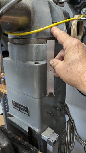
The top and bottom plates were TiG'd to the pipe and the weld was cleaned up, filled and radiused to blend into the pipe portion. The parts were clamped VERY securely and very small tack welds were alternated on opposite sides until there were 8 - 1/2" beads. I made sure everything was kept cool as I wanted zero warping. I unfortunately did not take pictures of the welding. The 1018 was a breeze to weld to the pipe. I am using 1/2-13 studs with long nuts / washers to clamp the entire assembly in place. Clearance through holes for the studs were bored to .563". This give the assembly a bit of wiggle room to get the studs threaded in to the internal clamping plate. The witness marks were easy to extend top and bottom. Measured parallelism between the top and bottom contact surfaces was .001 at worst and .000 at best. (I can live with that)
The turned the thickness of the top/bottom plates to add .750" each to the height. The tube was cut to 3.50" - so overall added height to the column is 5".
In retrospect - I kind of wish I had gone 4" oal - but this will work fine and give me plenty of room for the dividing head and other fixtures.
I need to color match the paint - first attempt was using a Ben Moore color recommended as a Clausing match - not even close. Second try later tonight.
I'll post more pics when it is the right color and all reassembled.
Sincere appreciation to the folks from the other thread for insight and plans - all of it was a huge help.
I ended up opting for a round column riser that fits between the head casting and the round transitional cap on the colum.
Through suggestions here and searching - a piece of DOM tubing was found on egay. It was 7" OD x .438" wall thk x 6" long.
Speedy metals supplied the top and bottom plates that were 1018 steel; 7.25" dia x 1.125" thk. Total cost of all the steel was under $175.
The design is a very close copy of the riser that joeuser01 posted on the thread started by Bill Gruby here: Riser Block Thread
I added steps to the top and bottom plates where the tube would contact them and cleaned up the ID of the tube as well to match for a snug / square fit.
Mounted on 5/8 arbor...........................RPM:575 0 nice finish w/ carbide......................Top of top plate ........................................ Underside of top plate
Top of the bottom plate.............................. Underside of the bottom plate ..............Tubing trued for length & ID
Test Assembled ................................................................................................................Checking fit on the column
Wet coat of paint (wrong color :-( )
The top and bottom plates were TiG'd to the pipe and the weld was cleaned up, filled and radiused to blend into the pipe portion. The parts were clamped VERY securely and very small tack welds were alternated on opposite sides until there were 8 - 1/2" beads. I made sure everything was kept cool as I wanted zero warping. I unfortunately did not take pictures of the welding. The 1018 was a breeze to weld to the pipe. I am using 1/2-13 studs with long nuts / washers to clamp the entire assembly in place. Clearance through holes for the studs were bored to .563". This give the assembly a bit of wiggle room to get the studs threaded in to the internal clamping plate. The witness marks were easy to extend top and bottom. Measured parallelism between the top and bottom contact surfaces was .001 at worst and .000 at best. (I can live with that)
The turned the thickness of the top/bottom plates to add .750" each to the height. The tube was cut to 3.50" - so overall added height to the column is 5".
In retrospect - I kind of wish I had gone 4" oal - but this will work fine and give me plenty of room for the dividing head and other fixtures.
I need to color match the paint - first attempt was using a Ben Moore color recommended as a Clausing match - not even close. Second try later tonight.
I'll post more pics when it is the right color and all reassembled.
Sincere appreciation to the folks from the other thread for insight and plans - all of it was a huge help.
Last edited:


.jpg")
.jpg")
.jpg")