Can This Motor Be Electrically Reversed ???

Bob, covers it well above.....the suggestion to temporarily remove the jumpers really helps.

The only thing I could add is that the resistance difference between six inches of those leads in your photo and the entire small-gauge start/run windings may be difficult to measure. Either motor winding may be only a fraction of an ohm, making it hard to tell which wire is really which........

-brino
 
Thanks so much to each of you who have replied. All very helpful. I'm pretty good with some things but the electrical innards of split phase motors isn't one of them. Regarding safety, funny brino mentioned that. I unplugged the power cord and draped it over the belt guard so the plug was in close proximity to my face. Note to self: If you can't see the naked plug, maybe it's not safe.

Life overtook my plans today so I had very little time to deal with it, but I did make some progress.

The four wires from the motor housing were all coated with grey paint (primer?) so I used acetone to remove enough paint to see if the insulation colors were unique. They aren't. From left to right in the photo of the terminal block, #1 is blue, #2 is green, #3 is also blue but I left the paint on it so I'm calling it grey, #4 is also green. The two green wires, #2 & #4, are of lighter gauge (maybe 18 or 20) than the other two (maybe 14 or 16). I found 1Ω across #1 and #3 (I presume they are the run winding). As predicted, there was momentary continuity across #2 and #4, then it went open.

At that point, reality intervened so I had to move on. Tomorrow, rather than unsoldering a capacitor lead, I'll do as RJSakowski suggested and check from either side of the capacitor to #2 and 4. I want to verify the function/connection of the centrifugal switch by spinning up the armature with a cordless drill. I plan to use a large pot magnet to couple the drill to the motor pulley. I should post a picture if it works properly.

Thanks again. Back tomorrow.
 
Today I verified that wires #2 and #4 are the start circuit. I swapped them and the motor runs in the reverse direction. Success (phase 1).

By the way, my attempt to use a pot magnet, stuck to the pulley, to spin up the armature and verify the function/connection of the centrifugal switch was a failure. I put a #10 machine screw through the hole in the center of 25 lb. pull pot magnet and tightened a coupling nut to secure. I chucked the coupling nut in a cordless drill (1500 RPM) and stuck the magnet on top of the pulley. It turns out that the coupling nut wasn't precisely perpendicular to the face of the magnet which caused the drill body to (try to) wobble when running. Also, it's not easy to get the magnet (coupling nut) concentric with the axis of the armature, resulting in another source of eccentricity. At probably a few hundred RPM, the wobbles overcame the magnet and it separated from the pulley. Thinking about it now, what I should have done was to NOT chuck the coupling nut in the drill motor. Instead, just place the magnet as accurately as I can, concentric to the armature axis, then use a nut driver w/universal joint in the drill to drive the coupling nut. The universal should forgive all sins. I'll try it tomorrow.

When I bought the machine, there was no cover or box over the terminal strip. I've decided to use a single gang bell box to enclose the terminal strip and mount a FWD/REV toggle switch. I'll post AFTER photos when that's accomplished.

Thanks again to the contributors who helped me with the electrical issues.
 
I'm glad you got what you wanted!
Another proof of desire and persistence paying off.

Thanks for the update.

-brino
 
I'm glad you got what you wanted!
Another proof of desire and persistence and knowledge paying off.

Thanks for the update.

-brino

I fixed it for you. Thanks again for contributing to the knowledge.
 
Bob, covers it well above.....the suggestion to temporarily remove the jumpers really helps.

The only thing I could add is that the resistance difference between six inches of those leads in your photo and the entire small-gauge start/run windings may be difficult to measure. Either motor winding may be only a fraction of an ohm, making it hard to tell which wire is really which........

-brino
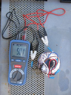
I bought this meter to compare resistance of windings of about 50 200va trannies for series/parallel connection. Despite them being identical, even down to the batch No., they varied by about 2 1/2 mOhms. Back to the point, an electrician friend showed me how to discriminate windings/shorted turns in a motor [have forgotten some of it] with this meter. He even mapped out the wires on a 12 wire washing machine motor which I later scrapped [too hard]. Readings will vary with temperature. $140 on Ebay.
John.

IMG_0310a.jpg
 
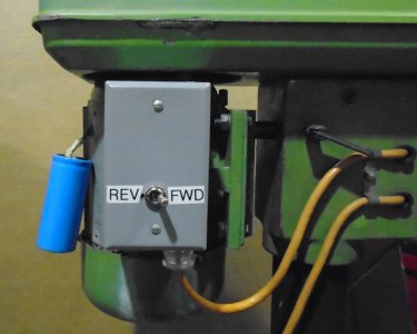
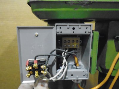
These photos show the implementation of a new junction box with reversing switch on a small import drill press.
One photo shows the start capacitor just hanging by it's leads. The capacitor cover that was on there when I bought the machine (used) is made of plastic and damaged beyond my interest in repairing it. I'll visit a motor repair shop soon and (hopefully) find a reasonable replacement. Other than the replacement capacitor cover, I'm declaring a victorious conclusion to this project. On to the next . . .
Thanks again to the contributors.

Drill Press Motor Junction Box Closed.jpg Drill Press Motor Junction Box Open.jpg
 
You may have a difficult time finding a replacement cover but you should be able to fabricate one fairly easily from suitable sized PVC or CPVC plumbing fittings. Couple of end caps, a short length of pipe, and a clamp or two and you're there. You could also use EL bracket(s) to fasten to the motor housing.

Congratulations on following through methodically and solving your problem. Always a good feeling.
 
Back
Top