-
Welcome back Guest! Did you know you can mentor other members here at H-M? If not, please check out our Relaunch of Hobby Machinist Mentoring Program!
You are using an out of date browser. It may not display this or other websites correctly.
You should upgrade or use an alternative browser.
You should upgrade or use an alternative browser.
Building a High Speed Punch Press
- Thread starter JimDawson
- Start date
- Joined
- Jan 28, 2011
- Messages
- 3,585
Jim, interesting project.
With the advent of laser, industry is GIVING away punch presses. Why didn't the customer want to just get one of these?
Not all metals take kindly to the heat of a laser. We have been looking at laser but not 100% replacement for us. So still using presses.
- Joined
- Feb 8, 2014
- Messages
- 11,176
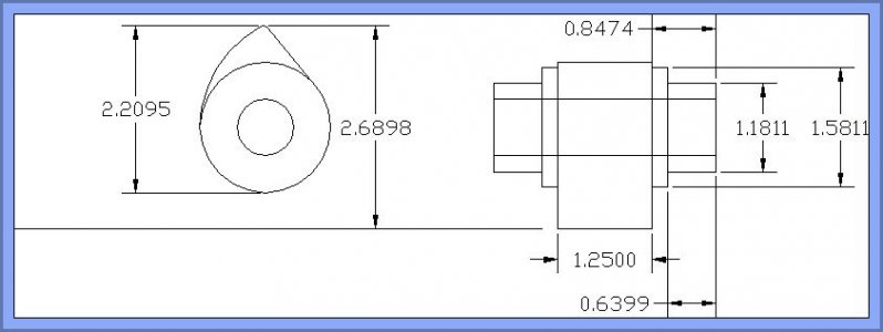
OK, a little teaser for the next and last phase of the press build.
The Cam
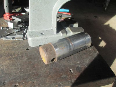
I have a piece of a 3 inch dia. pin, what I assume is a piece of pivot pin out of an excavator bucket hinge or something like that. As you can see on the end it still has a splotch of Caterpillar yellow paint. It's hard chromed with a surface hardness of about R70C, and the depth of the hard layer is about 0.080, so it is probably induction hardened also, it is probably 415o or similar alloy. I chose this because I need a pretty tough chunk of steel for the cam
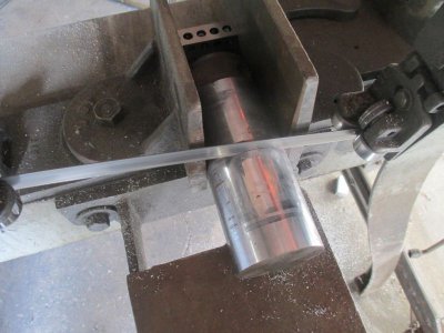
I need a rough diameter of about 2.700 for final machining, so I have to remove 0.300 from the OD. Now if I had a big beefy, 10HP lathe it would be no problem, I would just take a 0.100 depth of cut and get under the hard surface in one cut, but my lathe is only a 13x40, 2 HP, so that ain't gonna happen.
So the question is how do I cut it to about 3.500 rough length, and then turn it to size using the equipment I have?
(I'll post the pictures and explanation later)
The Cam

I have a piece of a 3 inch dia. pin, what I assume is a piece of pivot pin out of an excavator bucket hinge or something like that. As you can see on the end it still has a splotch of Caterpillar yellow paint. It's hard chromed with a surface hardness of about R70C, and the depth of the hard layer is about 0.080, so it is probably induction hardened also, it is probably 415o or similar alloy. I chose this because I need a pretty tough chunk of steel for the cam

I need a rough diameter of about 2.700 for final machining, so I have to remove 0.300 from the OD. Now if I had a big beefy, 10HP lathe it would be no problem, I would just take a 0.100 depth of cut and get under the hard surface in one cut, but my lathe is only a 13x40, 2 HP, so that ain't gonna happen.
So the question is how do I cut it to about 3.500 rough length, and then turn it to size using the equipment I have?
(I'll post the pictures and explanation later)
Last edited:
- Joined
- Feb 8, 2014
- Messages
- 11,176
The cam
As I said above, this has a hard surface about 0.080 thick, but the interior is machineable. I have made a couple of parts out of this material so I knew what to expect.
No problem cutting to rough length. I have an M42 bi-metal blade in my band saw, walked right through the material, slow speed and heavy feed. No coolant so it doesn’t work harden.
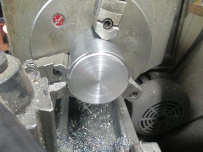
A test cut to figure out just how deep the hard area is. I used the brute force method of machining here. Using only the finest Harbor Freight AR-6 brazed carbide tool bit, I just started powering through the hard layer. About 0.020 DOC and 70 RPM (as slow as my lathe will turn), 0.010/rev feed. With the tool spring, it would only actually take about 0.010 DOC even though I dialed in 0.020. This was a process of taking a cut towards the chuck, then reverse the feed and let it also cut on the way back out. This presents a new cutting edge to the work. One cut, then reshapen the tool. Rinse/repeat until the hard surface is gone. I could only do half of piece at a time so once one half was done then flip it around and do the other end. The only goal here is just to get through the hard surface.
Once I removed the hard layer, then I faced the end and bored the 19mm center hole to prep the work for mounting on an arbor to do the actual machining. I want all of the surfaces concentric to the bore, so this is the first operation. Many times it’s all about order of operation. On any part that requires more than one operation, I machine the whole job in my head before I ever touch the machine. I know how I’m going to hang onto the work, what tools to use, feeds and speeds. That way I don’t have to think too much while I’m actually doing the work. I can concentrate on keeping my fingers out of the spinney things.
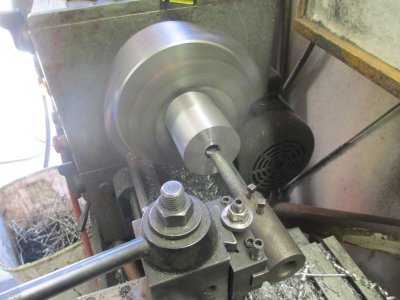
Prepping the arbor. I grabbed a chunk of 1.5 inch, 1020 shaft off of the rack to make the arbor. Normally I would not have this much stick-out for drilling the center hole because of the runout (about 0.010 at the end in this case) in the end of the shaft, but in this case I wanted the center on the lathe centerline and not in the center of the shaft. Once the turning is complete, the center will be in the center of the arbor, but not in the center of the original shaft.
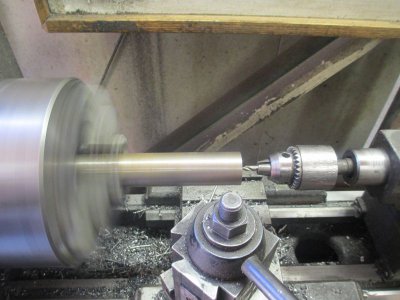
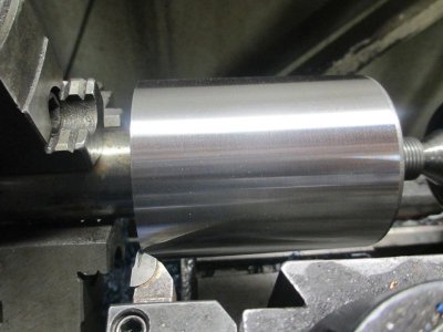
Using the same tool I used to remove the hard surface, I turned the arbor to size for a tight slip fit. I added a chip breaker to the tool because I hate long stringy swarf coming off the work. I need to note here that this tool bit has never seen my carbide grinder, all of the sharpening and shaping was done with a standard gray aluminum oxide grinding wheel on my bench grinder. The chip breaker was put in with the Dremel with a diamond wheel. Turning was done at 750 RPM, 0.005 feed. Tool bit just BELOW center and no nose radius, no spring back that way. As you can see the surface has a nice finish.
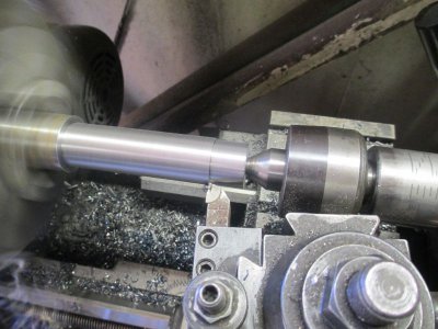
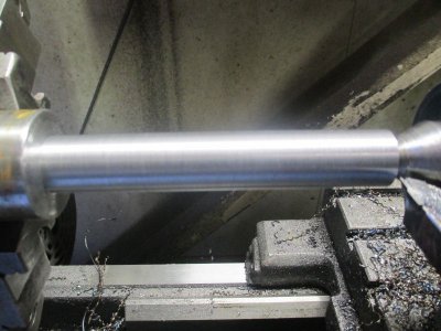
I grabbed another high quality Harbor Freight bit that I had modified for another project that was ground to about 60 degrees, I just cleaned up the grind on the bench grinder.
My old eyes don’t see as well as they used to so I put my headlamp under the tool to set the tool to the work.
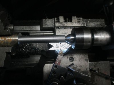
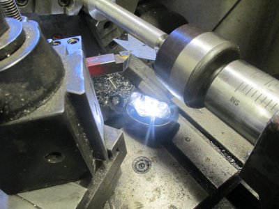
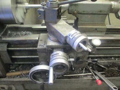
I prefer my cross slide handle to be set at the 9:00 position, makes it easier for me to back out at the end of the cut. Since 19mm is roughly 3/4 inch, I used a ¾ -16 thread.
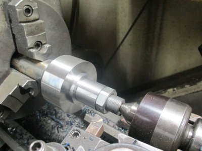
Now the work is mounted on the arbor, and the arbor will remain in the lathe until the work is complete. I can remove the work to swap ends and maintain concentricity with the bore.
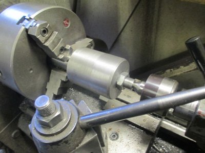
Now I need to take the OD down to about 2.700 to leave enough material to generate the cam shape, and do the work on the ends for the bearing journals. This material machines really nice. 0.020 DOC, 450 RPM, 0.005 feed, using the same tool as above.
More later!
As I said above, this has a hard surface about 0.080 thick, but the interior is machineable. I have made a couple of parts out of this material so I knew what to expect.
No problem cutting to rough length. I have an M42 bi-metal blade in my band saw, walked right through the material, slow speed and heavy feed. No coolant so it doesn’t work harden.

A test cut to figure out just how deep the hard area is. I used the brute force method of machining here. Using only the finest Harbor Freight AR-6 brazed carbide tool bit, I just started powering through the hard layer. About 0.020 DOC and 70 RPM (as slow as my lathe will turn), 0.010/rev feed. With the tool spring, it would only actually take about 0.010 DOC even though I dialed in 0.020. This was a process of taking a cut towards the chuck, then reverse the feed and let it also cut on the way back out. This presents a new cutting edge to the work. One cut, then reshapen the tool. Rinse/repeat until the hard surface is gone. I could only do half of piece at a time so once one half was done then flip it around and do the other end. The only goal here is just to get through the hard surface.

Once I removed the hard layer, then I faced the end and bored the 19mm center hole to prep the work for mounting on an arbor to do the actual machining. I want all of the surfaces concentric to the bore, so this is the first operation. Many times it’s all about order of operation. On any part that requires more than one operation, I machine the whole job in my head before I ever touch the machine. I know how I’m going to hang onto the work, what tools to use, feeds and speeds. That way I don’t have to think too much while I’m actually doing the work. I can concentrate on keeping my fingers out of the spinney things.

Prepping the arbor. I grabbed a chunk of 1.5 inch, 1020 shaft off of the rack to make the arbor. Normally I would not have this much stick-out for drilling the center hole because of the runout (about 0.010 at the end in this case) in the end of the shaft, but in this case I wanted the center on the lathe centerline and not in the center of the shaft. Once the turning is complete, the center will be in the center of the arbor, but not in the center of the original shaft.

Using the same tool I used to remove the hard surface, I turned the arbor to size for a tight slip fit. I added a chip breaker to the tool because I hate long stringy swarf coming off the work. I need to note here that this tool bit has never seen my carbide grinder, all of the sharpening and shaping was done with a standard gray aluminum oxide grinding wheel on my bench grinder. The chip breaker was put in with the Dremel with a diamond wheel. Turning was done at 750 RPM, 0.005 feed. Tool bit just BELOW center and no nose radius, no spring back that way. As you can see the surface has a nice finish.


I grabbed another high quality Harbor Freight bit that I had modified for another project that was ground to about 60 degrees, I just cleaned up the grind on the bench grinder.
My old eyes don’t see as well as they used to so I put my headlamp under the tool to set the tool to the work.


I prefer my cross slide handle to be set at the 9:00 position, makes it easier for me to back out at the end of the cut. Since 19mm is roughly 3/4 inch, I used a ¾ -16 thread.

Now the work is mounted on the arbor, and the arbor will remain in the lathe until the work is complete. I can remove the work to swap ends and maintain concentricity with the bore.

Now I need to take the OD down to about 2.700 to leave enough material to generate the cam shape, and do the work on the ends for the bearing journals. This material machines really nice. 0.020 DOC, 450 RPM, 0.005 feed, using the same tool as above.

More later!
- Joined
- Feb 8, 2014
- Messages
- 11,176
Here is the cam roughed out, the bearing journals are on size but I left the one side a bit long so I would have more to grab onto for the next operation.
While I was making roughing cuts I was playing with the tool height. This is where I got the best result. About 1/8 inch below center. A good finish, and no spring back. It cut exactly what I dialed in.
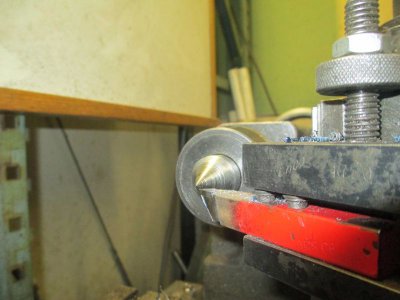

While I was making roughing cuts I was playing with the tool height. This is where I got the best result. About 1/8 inch below center. A good finish, and no spring back. It cut exactly what I dialed in.

- Joined
- Feb 8, 2014
- Messages
- 11,176
you may need to 'splain how that happens. . .
If you are asking about running the tool below center, I may have an answer. I know it goes against everything we have been taught. I think it presents an effective positive rake on the cutting edge, and the cutting edge is better supported than running on or above center. Also as the tool wears, there is still clearance between the tool and the work rather than rubbing. Also you are cutting on the top of the tool rather than the front edge. Like a tangential tool maybe? Maybe that's the answer, not sure.
I am not totally sure about why this works but it does, and I can't argue with success. I had to make quite a few passes to turn this piece and a just kept lowering the tool on each pass until I got no spring. In this case I was making passes at about 0.030 DOC (0.060 off of the OD)
Anyone feel free to jump in here if you can explain it better.
- Joined
- Feb 8, 2014
- Messages
- 11,176
No comment on the 1/8 below center, can't argue with success ! I'm waiting for the cam generation, LOL !
Hold my beer and watch this!!!
- Joined
- Feb 8, 2014
- Messages
- 11,176
Finishing the cam
The first order of business is to make a new set of soft jaws for the mill vice. I’ve run out of places to machine on the current ones. I’m out of 1-inch aluminum so I grabbed a chunk of 7/8 x 6, C1018. I’ll use these in the vice until I chew them up so much that I need to replace them. I have a set of hard jaws, but rarely use them.
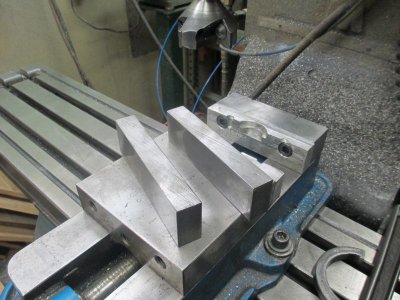
Squared up, drilled and counter sunk, ready to bolt in.
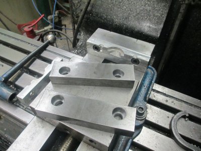
I put a couple of 3/8 dowel pins in to tighten against while milling the pocket
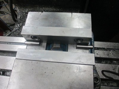
Milling the pocket to fit the cam bearing journal
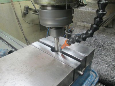
A quick deburr with the counter sink. Same g-code, just adjusted the knee height,
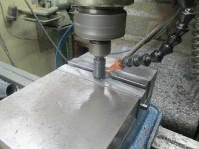
Ready to start machining the cam.
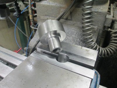
It’s starting to look a bit cam like. I’m using a ½ inch, high-shear, aluminum cutting, 2-flute end mill. I didn’t have a 4 flute long enough to do the job. If I would have had a long rougher I would have cut the rough profile in 2 passes, but I didn’t so ya use what ya got. 3 IPM feed, 90 FPM on the spindle, 1.250 DOC, 0.020 step over per pass. About 20 passes. WD-40 in the coolant tank (the red tank).
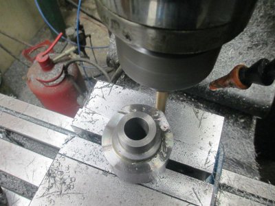
The finished profile. The surface finish came out much better than expected, that high-shear end mill did a nice job. It’s not really designed for cutting 4150. I’m surprised it lasted for the whole job; it made a lot of chips, or in this case about 1.25 long needles. Nasty little things.
The cam is a series of 3 blended arcs and one straight line. It could have been done manually on a drafting board then machined on a rotary table but it would not have been fun and would have taken a long time with several setups. I don’t know if I would have done it without a CNC. I have always designed things to be built on the tools I have available, so getting a CNC mill opened up a whole new world.
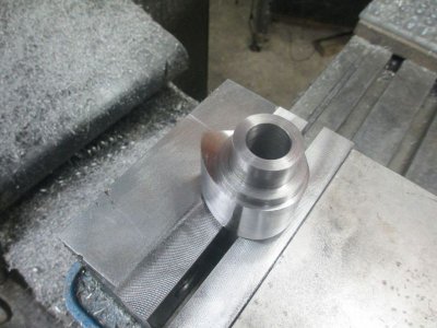
And there it is on the motor shaft.
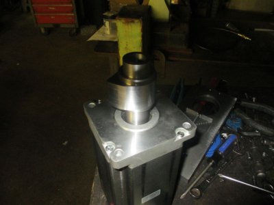
I still have to put in the keyway and the set screws
The first order of business is to make a new set of soft jaws for the mill vice. I’ve run out of places to machine on the current ones. I’m out of 1-inch aluminum so I grabbed a chunk of 7/8 x 6, C1018. I’ll use these in the vice until I chew them up so much that I need to replace them. I have a set of hard jaws, but rarely use them.

Squared up, drilled and counter sunk, ready to bolt in.

I put a couple of 3/8 dowel pins in to tighten against while milling the pocket

Milling the pocket to fit the cam bearing journal

A quick deburr with the counter sink. Same g-code, just adjusted the knee height,

Ready to start machining the cam.

It’s starting to look a bit cam like. I’m using a ½ inch, high-shear, aluminum cutting, 2-flute end mill. I didn’t have a 4 flute long enough to do the job. If I would have had a long rougher I would have cut the rough profile in 2 passes, but I didn’t so ya use what ya got. 3 IPM feed, 90 FPM on the spindle, 1.250 DOC, 0.020 step over per pass. About 20 passes. WD-40 in the coolant tank (the red tank).

The finished profile. The surface finish came out much better than expected, that high-shear end mill did a nice job. It’s not really designed for cutting 4150. I’m surprised it lasted for the whole job; it made a lot of chips, or in this case about 1.25 long needles. Nasty little things.
The cam is a series of 3 blended arcs and one straight line. It could have been done manually on a drafting board then machined on a rotary table but it would not have been fun and would have taken a long time with several setups. I don’t know if I would have done it without a CNC. I have always designed things to be built on the tools I have available, so getting a CNC mill opened up a whole new world.

And there it is on the motor shaft.

I still have to put in the keyway and the set screws
Last edited:
