-
Welcome back Guest! Did you know you can mentor other members here at H-M? If not, please check out our Relaunch of Hobby Machinist Mentoring Program!
You are using an out of date browser. It may not display this or other websites correctly.
You should upgrade or use an alternative browser.
You should upgrade or use an alternative browser.
Bridgeport Series 1 Boss3 LinuxCNC Conversion
- Thread starter Shotgun
- Start date
- Joined
- Aug 13, 2020
- Messages
- 1,342
It's a generic VFD that I'll be driving the stock motor with. I'm going to investigate if I can add an encoder. If not, I'll drive the motor at a fixed 60Hz, and use the mechanical speed control. If I can use an encoder, I'll allow the frequency to vary from 40Hz to 80Hz, controlled via the computer. I'll set the mechanical control to the desired speed, as best I can, and then the computer can keep it on the money. That way, I'll expect the speed range to be just slightly wider than the typical Bridgeport.
- Joined
- Feb 25, 2021
- Messages
- 3,271
I'm still holding out for an Ethernet interfaced Mesa card as they're well supported by the LinuxCNC software. They're saying it is likely another 3-4 months before any are available, but I have plenty to do to keep me busy this summer.In any case, don't buy the BOB I linked to. 'cause, you gotta be kidding me. . .
I don't know if that capacitor is supposed to be in that position or not, but the cold solder joint there and in other places just makes me cringe. And if they have some documentation of the pin out other than the markings on the board, they're doing a bang-up job of hiding it.
I'm going to write this one off as a $30 lesson in "don't be such a stupid cheap jerk."
- Joined
- Apr 23, 2018
- Messages
- 6,880
In case you wanted original information on that A-ha, I found a video that covers it.
- Joined
- Aug 13, 2020
- Messages
- 1,342
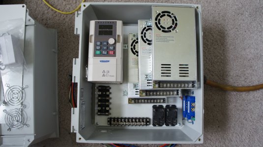
Got the power box put together this weekend. My system will have two 12.5"x14"x6" boxes, one for power and the other for control. One would think there would be a well thought out reason for that. My reason is the boxes were free. I inadvertently created a conflict between the VFD and connectors to the control box, so I'll need to relocate them just below the labels on the bottom left. I have a 14-pin cannon connector for all of the power circuits, and a DB-15 for signal level circuits. Two of the outlets will be switched (coolant and oiler), and the other two will be for lamps/fans/convenience, etc. Also, the power to the motor will exit the top of this box. Gotta drill a hole for that.
Yes. The fan function of the power supplies is compromised. Its a result of packing 10lbs of shinola into a 5lb box. (Don't ask me why the box weighs 5lbs.). But, everything is the box will be pushing air up, including the chimney effect, and there will be vent fan in the top right corner.

Yes. The fan function of the power supplies is compromised. Its a result of packing 10lbs of shinola into a 5lb box. (Don't ask me why the box weighs 5lbs.). But, everything is the box will be pushing air up, including the chimney effect, and there will be vent fan in the top right corner.

- Joined
- Aug 13, 2020
- Messages
- 1,342
Progress report:
- I got all the hardware rounded up and installed in a box. Actually, two boxes.
- I've verified that the OPi5 can ping the Mesa7i96s. Don't have mesaflash on the Pi, so I wasn't able to get a report from the card.
- I've run through PncConf, but so far I've not been able to get any of the motors to move. I have everything except the Pulse and Dir of each motor disconnected for now.
- Joined
- Aug 13, 2020
- Messages
- 1,342
Good news report:
I finally got the motors to turn today. Up to this point, all I've gotten is violent shaking from them. Found I was using the documentation for v3 of the driver boards, and the kit I bought came with v4 boards. Not much changed, except that I found out I could run them open loop. Something is seriously wonky with the encoders on these thing. Open loop is not what I paid for, but the motors ran just fine without them and I can move on to other challenges while I get that part sorted out.
The motors are able to do 50 IPM without doing any tuning. Not bad, considering the 10tpi leadscrew that the BP has. Of course, that was not driving a load.
I've also swapped out some parts.
The bus bar made way for a DIN rail. I've never used DIN before. Now I know why it is so popular with machine control electronics. The flexibility is incredible. And, it is low cost.
The two relays (bottom-right corner in the picture above) are making way for some relay modules meant for the Arduino world. 5V will switch 10A of 120V. The relays I had required 24V to switch, and the Mesa 7i96s I'm using only does 5V. I'm going to see if I can find a way to mount it to the DIN rail.
I'll get better pictures tomorrow. Right now, it's time for some Bulleit.
- Joined
- Aug 13, 2020
- Messages
- 1,342
I got the base of the mill cleaned up yesterday, and moved close to its final destination tonight.
I have been slowed down by the technology from getting the steppers to work properly. The initial testing of the OrangePi5 indicated that it would be an incredibly good candidate for the control computer. But, matching it with the Mesa 7i96s board brought the ethernet port into the mix, and it didn't play well. The control computer needs to write to the 7i96s every millisecond or so, and that write was taking too long on occasion. This results in a failure, and an end to the program.
Tonight, with help from the guys at LinuxCNC, I determined that the interrupt ports have to be tied to the same CPU cores that LinuxCNC is running its real-time thread on. As all things computer, it's easy to do, once you know it needs to be done.
- Joined
- Aug 13, 2020
- Messages
- 1,342
The hard part about a good tutorial post is remembering to update the thread with the changes you have to make once that original plan meets the enemy. After I had to switch up the Mesa board due to availability, I found out that the one I got didn't support 24V controls. Only 5V outputs, and one 0-10V PWM output, meant to control a VFD. That meant the original relays I had on hand wouldn't work. But, I found these:
So now the Power Box looks like this.

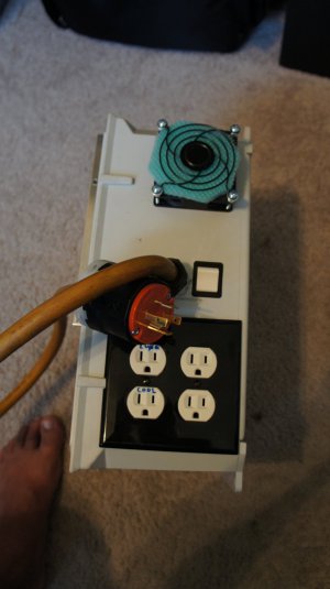
Power comes in via a 220V, 4-prong, lock plug. L1 and L2 pass through a 30A, DPST switch.

Inside, one leg goes from the switch over to the left-bottom to a bank of fuses. The other leg goes to the set of red DIN connectors at the bottom. Three are ganged together, to give me five branch points. The Neutral leg goes to the three gray connectors on the left, once again ganged. The ground is picked up by the green-yellow that is ganged with three gray. The kit only had one green-yellow for some reason.
Counting up. The first fuse feeds the two relays on the right side of the DIN rail. The relays are 5V controlled, and the wires for that come in through the DB15 connector on the left. They need to be powered by 5V from the Control Box, and then a 5V control signal. The relays control the outlets with the blue markings, which read coolant and lube. Which one does what is left as an exercise for the reader.
The second fuse up send power to the auxiliary outlets. One of these is taken already by the monitor. The other will most likely be some sort of work light.
The next three fuses got to each of the X, Y, Z stepper power supplies. I could have run these off 120V, but 220V reduces the current draw. The other leg is unfused, but breaking one leg breaks the circuit.
In the same way, the top fuse supplies one leg of 220V to the VFD. The VFD is controlled via 2-wire RS-485, coming in through the DB-15.
The stepper power supplies feed the Control Box via the cannon plug on the left. The VFD will control the motor via a gland on the top of the box. Barely visible on the bottom left is the filter for incoming air. Above the power cord is an externally mounted exhaust fan. I may need to add exhaust power, but the VFD and supplies all have fans, and they all are pushing air up. I'm hoping that with the chimney effect, it will be enough. But, I do have one of those later thermometers to test the temp gradients.
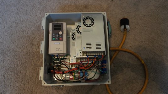
Next up will be the Control Box. I have it mostly done, but I still need to wire in the limit switches and the original power controls. I'm also still wondering if there is a way to connect a spindle encoder to a BP.
So now the Power Box looks like this.

Power comes in via a 220V, 4-prong, lock plug. L1 and L2 pass through a 30A, DPST switch.

Inside, one leg goes from the switch over to the left-bottom to a bank of fuses. The other leg goes to the set of red DIN connectors at the bottom. Three are ganged together, to give me five branch points. The Neutral leg goes to the three gray connectors on the left, once again ganged. The ground is picked up by the green-yellow that is ganged with three gray. The kit only had one green-yellow for some reason.
Counting up. The first fuse feeds the two relays on the right side of the DIN rail. The relays are 5V controlled, and the wires for that come in through the DB15 connector on the left. They need to be powered by 5V from the Control Box, and then a 5V control signal. The relays control the outlets with the blue markings, which read coolant and lube. Which one does what is left as an exercise for the reader.
The second fuse up send power to the auxiliary outlets. One of these is taken already by the monitor. The other will most likely be some sort of work light.
The next three fuses got to each of the X, Y, Z stepper power supplies. I could have run these off 120V, but 220V reduces the current draw. The other leg is unfused, but breaking one leg breaks the circuit.
In the same way, the top fuse supplies one leg of 220V to the VFD. The VFD is controlled via 2-wire RS-485, coming in through the DB-15.
The stepper power supplies feed the Control Box via the cannon plug on the left. The VFD will control the motor via a gland on the top of the box. Barely visible on the bottom left is the filter for incoming air. Above the power cord is an externally mounted exhaust fan. I may need to add exhaust power, but the VFD and supplies all have fans, and they all are pushing air up. I'm hoping that with the chimney effect, it will be enough. But, I do have one of those later thermometers to test the temp gradients.
Next up will be the Control Box. I have it mostly done, but I still need to wire in the limit switches and the original power controls. I'm also still wondering if there is a way to connect a spindle encoder to a BP.
- Joined
- Aug 13, 2020
- Messages
- 1,342
I've been making steady progress, after some seriously big road bumps.
The first was that steppers from Stepper-Online don't like extra connectors spliced into the supply or encoder lines. The goal was to have quick disconnects on the exterior of the control box. so that it would be easy to take it off and go inside with it. Instead, each wire enters through a gland and is connected directly to the appropriate driver.
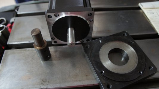
Then I made plates to adapt the steppers to the Boss3. Actually, I partly made them. The Boss3 steppers have a plate on the drive end that you can tap off fairly easy after removing four long screws with a straight-head screw driver. These same four holes, situated at an odd angle, can be tapped for 1/4-20 and used to secure the Nema-34 motors. I did chuck them in the 4-jaw, indicate them on the center hole, and turn a relief that centers the short boss on the drive end of the Nema-34s. Bolting the steppers to those plates, replacing the pulleys, and it bolted right up to where the old steppers were.
I then made adapters for the 14mm shafts to the 5/8 that was on the Bridgeport steppers.

I don't have an arbor to make a keyway, so I opted for two set-screws in the adapter.
Then I ran into a situation where if you run the Z axis too far in the positive direction, it will wedge itself into a position where it take a lot of muscle to get it reversed. That led to meticulous, and very careful limit switch setup.
I've been through several rounds of configuration on LinuxCNC, but I now have homing and movement working correctly. I'll eventually post my settings here, but that is really just something that has to be worked through.
The currently hurdle is getting the VFD to work via RS485 commands from LinuxCNC. This is where the cheap VFD from a Chinese company called 'Mollum' demonstrates why you should buy an expensive American one, if you've got the cash. So far, I've been able to get the spindle to run in the forward direction. But I wasn't able to turn it off.
The saga continues.
The first was that steppers from Stepper-Online don't like extra connectors spliced into the supply or encoder lines. The goal was to have quick disconnects on the exterior of the control box. so that it would be easy to take it off and go inside with it. Instead, each wire enters through a gland and is connected directly to the appropriate driver.
Then I made plates to adapt the steppers to the Boss3. Actually, I partly made them. The Boss3 steppers have a plate on the drive end that you can tap off fairly easy after removing four long screws with a straight-head screw driver. These same four holes, situated at an odd angle, can be tapped for 1/4-20 and used to secure the Nema-34 motors. I did chuck them in the 4-jaw, indicate them on the center hole, and turn a relief that centers the short boss on the drive end of the Nema-34s. Bolting the steppers to those plates, replacing the pulleys, and it bolted right up to where the old steppers were.
I then made adapters for the 14mm shafts to the 5/8 that was on the Bridgeport steppers.

I don't have an arbor to make a keyway, so I opted for two set-screws in the adapter.
Then I ran into a situation where if you run the Z axis too far in the positive direction, it will wedge itself into a position where it take a lot of muscle to get it reversed. That led to meticulous, and very careful limit switch setup.
I've been through several rounds of configuration on LinuxCNC, but I now have homing and movement working correctly. I'll eventually post my settings here, but that is really just something that has to be worked through.
The currently hurdle is getting the VFD to work via RS485 commands from LinuxCNC. This is where the cheap VFD from a Chinese company called 'Mollum' demonstrates why you should buy an expensive American one, if you've got the cash. So far, I've been able to get the spindle to run in the forward direction. But I wasn't able to turn it off.
The saga continues.
