Belt drive for large diameter lazy susan platform

Reddinr

H-M Supporter - Diamond Member
H-M Lifetime Diamond Member
Joined
Jan 5, 2014
Messages
995
I'm looking for ideas on an upcoming project I have. I need to make a one-off for a customer and I'm a little stuck on something.

The project needs to servo-drive a large diameter platform, something like a 24" diameter lazy-susan. I need to turn it slowly, in one direction only, maybe up to 30 RPM at most. It needs to be fairly precise in the commanded angle. It needs to be very quiet and smooth when operating. I'm thinking about using a Type L timing belt and pulleys. I had considered gears but I think those might couple too much servo / gear noise to the platform. The pulley on the servo might be about 1.4" diameter, the smallest I can get. The platform pulley will be milled into the underside of the platform and will be about 16-18" diameter. This gives me a decent reduction ratio. The platform will either be plywood or plastic. Undecided.

With the speeds I'm thinking about I am wondering if I couldn't just purchase a timing belt, turn it inside out and glue it to the big pulley instead of having to mill 135 or more teeth precisely into the big pulley. Then I would run the actual timing belt over the top of that one. I know it doesn't mesh exactly but maybe it would work since the gaps are wider than the teeth and I only have to turn in one direction. The platform will weigh about 3-4 pounds including load and acceleration/deceleration can be kept very low.

Any pointers or ideas for the power transmission would be very helpful! Thank you.
 
To isolate the servo and to be lazy...compound it.

First look at timing gears as the camshaft end on some are fairly large.

Crankshaft end too large center hole but smaller gear easier to make if needed.

Use the cam gear on turntable driven by smaller gear connected to another cam gear making compound gear.

Drive that with another on the servo.

That gives 2 belts to isolate the servo and may allow more compact layout by allowing motor to be placed under turntable

Sent from my SAMSUNG-SM-G930A using Tapatalk
 
Don't know why that wouldn't work. As long as it only turns in one direction it should load properly. The OD of the platform pulley would have to be exactly the correct diameter to get the ends of the belt to match up properly.

On the other hand, machining the pulley shouldn't be that difficult either, should be able to do it in 2 passes. The HDT tooth form is a bit easier to machine.
 
An automotive ring gear from a flex-plate might work well with the right coged belt. Plenty available cheap in the junk yard, or direct drive with a matched starter gear. Mike
 
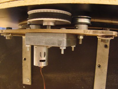
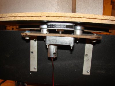
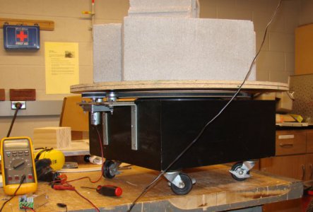
I did a turntable to rotate a person for full body scanning for my son. I used a small DC motor with a gear box. Purchased a toothed-belt pulley to fit the motor shaft. Made a large diameter pulley out of 1/2" MDF sandwiched between two 1/8" hardboard, mounted under the platform. I added two idlers on the motor mount to take up slack and increase the amount of the toothed-belt around the motor pulley. It worked down to a creep and up to about 30RPM with a 200 Lb load. The amount of friction contact between the toothed-belt and the large platform pulley was great enough that I never saw any slippage Powered the motor with a cheap PWM controller. I selected the belt length by setting up the belt path in CAD.

With a "servo" are you intending to precisely control the angle of rotation?

Ken

Motor drive.jpgMotor drive1.jpgTurntable.jpg
 
Last edited:
As a Model Railroader, of the steam era, your project sounds a lot like a medium sized turntable. In my scale, HO, a 16 inch table would be middlin large, capable of taking a fair sized locomotive. The desired speed would be a little slower, with the "alignment" being on the order of 0.020 inch. The rail is 0.085 in height, with the width less than a third of that. Such precision is necessary because models will run across the joint, albeit at low speed.

There are many drive mechanisms for such applications. My personal favorite was one I saw in 1970 where a fellow modeler had used an audio turntable drive mechanism with a rubber wheel against a plywood disk. Alignment was controlled with a spring loaded pressure against the disk that retracted on command of a sensor that aligned the rails. For what it's worth, it was in Wellington, N.Z. that I saw this.

Granted, the travel was a bit slower than you're talking, ca. 2-3 RPM, and the load was quite low, on the order of a few pounds. Brass models in that scale, plus the weight of the structure itself. But the overall drive mechanism was fairly simple. Perhaps investigating such model turntable drives will yeild an approach that is usable for your application. There are many that are based on fancy technology, but the rubber wheel against a plywood disk gets my attention even after all those years. In most cases, quietness is secondary to accuracy but still important.

It would be a matter of the weight necessary to handle and the accuracy when stopping from speed that would come into play. I like the idea about the toothed belt inverted to provide a ridged surface to pull against. The buggest problem I foresee is the concentric rotation of the disk.

Bill Hudson​

Edt: The above entry is quite adaptable, an elegant solution. I may well integrate a similar drive mechanism for my own applications.
 
Last edited:
I am curious if this is something for a one-time use or is expected to maintain accurate positioning for years. Does it need to maintain angle registration between use or can it be "zeroed" before each use? Does it need to maintain absolute angle accuracy over multiple revolutions or just one revolution? What is the actual Angle accuracy needed. I think these are important things to know to determine if a gear train or pinch-roller or something in between will meet the need.
 
Thanks all.
Kmoffit, you hit the nail on the head. Pretty much what I had in mind except I didn't think about using idlers to make the belt wrap around the small pulley, which I will now do. The motor looks like one I saw at All Electronics that I was thinking about using. Can you recall what kind of backlash the gearbox had? I do need to be precise with the angle.

The rubber wheel idea might also work but I would be concerned about slippage by tiny increments over time. BTW, I was fortunate to spend a couple of weeks in NZ myself. Loved the country and the people I met were just terrific.

I'll need to check out the ring gear idea too.

Next up I'll need to figure out how to support the thing from the perimeter. I need to keep the middle 90% of the underside of the platform clear of anything. I'm thinking small nylon or hard rubber bearings or similar. The nylon / ball bearing ones like for a closet door track come to mind. The load is low, maybe 3-4 pounds total.

As far as the belt type, I picked "L" because I could easily find longer lengths of it. Not sure about the HDT type. Will look. I am all for a simpler profile.
 
The angle can be re-zeroed between uses. The typical usage time will be about an hour and there might be 1000-2000 complete revolutions per use. Absolute accuracy must be maintained for the entire time. I would be shooting for +/-0.1 Degrees for one revolution and +/- 0.5 Degrees for the entire session. I will have an encoder but not sure where in the drive train it will be placed yet.
 
The angle can be re-zeroed between uses. The typical usage time will be about an hour and there might be 1000-2000 complete revolutions per use. Absolute accuracy must be maintained for the entire time. I would be shooting for +/-0.1 Degrees for one revolution and +/- 0.5 Degrees for the entire session. I will have an encoder but not sure where in the drive train it will be placed yet.

Encoder should be on the final load. Anywhere else may not represent the position of the load
 
Back
Top