Balanced Grinder Hubs

Benny,

.............................. I do not understand what you mean by the pattern adapter. If you hum a few bars, I'll try to whistle along............... I'll gladly post the CAD drawing if you want it.
Ray

What I meant by "pattern adapter" was since we had no drawing or knowledge of what an adapter dimensions should be we would use the one existing adapter on my surface grinder as a pattern to "reverse engineer" and make additional adapters. A drawing with real dimensions and tolerances would be nice. Likewise, Charley has a fairly complete set of tools for install and removal of grinding wheels that we could copy to make additional tools for me since no tools came with my surface grinder.

Benny
The Orphanage Never Closes
 
For grinder acessories such as wheel hubs and high speed belts, look up the William Sopko Company; they have adaptor hubs for a number of makes of small surface grinders and tool & cutter grinders.
 
Yes, Sopko seems like the go-to place for grinder stuff but there's one small problem... I called them three years ago when I got my SG and the balancing grinder hubs were running about $800 each. -Ouch! I'd like to have about four units as that's how many wheels I do most of my work with. This is probably the one time in my life when I'm making something that will be cheaper than purchasing it...

Ray


For grinder acessories such as wheel hubs and high speed belts, look up the William Sopko Company; they have adaptor hubs for a number of makes of small surface grinders and tool & cutter grinders.
 
IMG_0073[1].JPGjust a rough sketch of what my weights look like, being tapered, if they werent split , you couldnt get them inside the groove. The taper wasnt that much, im thinking it was about 15 degrees but its been over 10 years since i ground rolls so im not sure

IMG_0073[1].JPG
 
The thread about B&S taper reamers (http://www.hobby-machinist.com/show...r-Straight-shaft-w-o-spinning-between-centers) has come to a close. The purpose of the reamer was to complete these balanced grinder hubs and we're in a position to resume... You might want to look at the first few posts of this thread to refresh your memory.

When making these, it's important to plan the sequence of operations. I'm going to do all the backside work first and have chosen the rear face as the starting geometry. There is plenty of meat on the blank part so there's plenty of room to bring all the other dimensions in line.

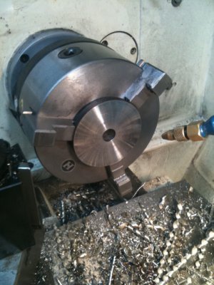
First, the piece is propped with parallels to give a little clearance to face the back. Always remember to remove the parallels before spinning-up. A base hole is drilled all the way through as a starting point for the taper cut. The material is 1045 and it's already been fully normalized. It's very easy and nice to work with and the ER80s welds caps came right off.
CS1.JPGCS2.JPG

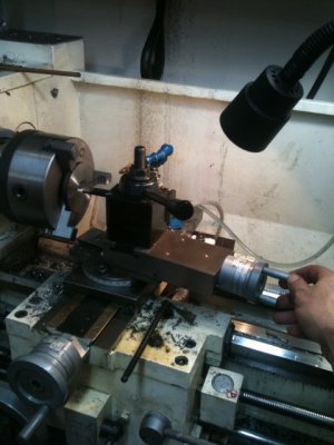
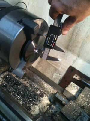
Next, the taper is cut by critically setting the compound angle and using only compound travel to move the boring bar. I've shown many times how to use DIs and make Rise over Run setups and this is how the angle of 7.125[SUP]o[/SUP] was set here. If you need help with that, let me know and we'll go over it more closely.

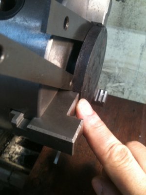
The cross slide is moved back to take 15 thou DoCs until the backside diameter is just shy of one inch. I stopped at roughly 0.995". It's hard to make that measurement since there's no real lip but, in this case, close enough is good enough. The depth of the taper is predefined by geometry and I keep pushing in until it stops cutting. Remember to lock the compound and disable any possibility of engaging autofeed. This is close work to the chuck and you'll crash in a heartbeat. BTW: I used the "outside" jaws because the other set would not allow me to insert the stub part of the hub in the chuck bore.
CS3.JPGCS5.JPG

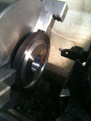
A groove is needed to accommodate some balance weights. I don't use this groover often but it's handy. It needs a new carbide insert and I can't seem to locate one. Any clues folks on where to get them? Anyhow, I'll be making many of these (4 more) so, the groove will be uniformly placed on all units.
CS6.JPG


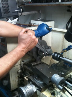
Safety note: In this procedure, the lathe safety is engaged and the unit is powered off. I think you know why.

The taper reamer that was just made earlier is inserted, light pressure from the tailstock is applied and it's manually cut. Happy to report, the cutter went through the metal like butter. Nice even swarf piled up in the flutes. I realize now though, I should cut the flutes about 20 thou deeper as the cutter would quickly pack up and need to be wiped clean. (and yes, that's a bad angle on my wrist but I was forced into that because I can't put too much pressure on the fingertips yet).

The taper came out very nice and the ending hole size is about dead on at 1" -which is what is needed for the arbor on my particular surface grinder.
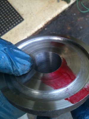
CS8.JPGCS9.JPG

More later

Ray

CS1.JPG CS2.JPG CS3.JPG CS5.JPG CS6.JPG CS8.JPG CS9.JPG
 
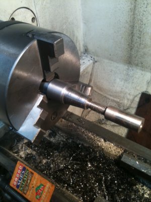
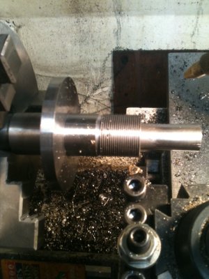
OK, here's the finished hub. To finish it, the special spindle was made (quite some time ago) to mount the hub then, you keep carving away until all the exterior dimensions are met -except, I leave about 0.002" (1.252" Dia) on the shaft diameter where the wheel sits. Cut the threads to the appropriate size (1.25" x 18 TPI-LH). The spindle must be mounted carefully and run true. Although not shown in the picture, there's a center hole in the end of the shaft which was supported by a live center while all the external dimensions were cut. After the threads are cut, it's checked on the grinder.

This one is running very true but I can indeed feel the slightest bit of vibration. -No worries... The part will be heat treated and when it's done, the inner taper will be touched-up with the reamer and then, it will be mounted on the actual surface grinder, spun up to about 1000 RPM and with a tool holder mounted on the mag base, I'll trim that last 0.002" off.

I know this sounds a little crazy but, I've made a few of these things before and if it's not done in the proper sequence, you'll stand little chance of the final product spinning perfectly. I have done it before without finishing it on the actual grinder but, it takes a LOT of setup time. This is a shortcut that works very well.

BTW, if you purchase these brand new, they cost a fortune (Sopko wants about $800 for them).

Surface grinding with a perfectly balanced wheel is like the difference between night and day...


SA1.JPGSA2.JPG

Ray

SA1.JPG SA2.JPG
 
a bit off topic (beautiful machine work by the way), but has anyone thought about making an auto-balancing hub? They make them for Nascar and for high speed centrifuges (13,000rpm+). The basic premise (I think) is that there is a cavity inside the hub that's has a number of small ball bearings loose in it. When the hub (or rotor in the centrifuge) spins up, these are supposed to distribute themselves around the inside of the hub to balance it. I saw one of the centrifuges in action and it was seriously impressive.

That's about all I can contribute though as I'm not much of an engineer!
 
I've heard of systems similar to this that worked with mercury instead of ball bearings. It's intriguing indeed and seems (at the surface) easy to build but, sometimes things are deceivingly difficult.

I'll let you know what I come up with...

Ray

yeah, simple ideas and simple implementation = already done :)

Presumably you'd need a balancing material that has a fine enough resolution to counteract all of the imbalances in the wheel, yet moves freely enough to not clump or introduce its own imbalances. I guess it also depends on the inside diameter of the hub too. You can get really tiny ball bearings though. I can't remember the size of the ones in my mtb pedals, less than 1/8in for sure, but something along those lines might be an option. Wouldn't really want to work with that volume of liquid mercury to be honest!

here are some links I found, not all of which may be useful:
http://www.medicalautomation.org/2010/07/self-balancing-centrifuge-rotor/
http://www.google.com/patents/US4412831
http://www.google.com/patents/US3692236
http://www.innovativebalancing.com/index.php
 
Oh for sure... I wouldn't mess around with mercury. Ball bearings would probably be the way to go. I agree, the issue is allowing them to self-distribute without getting jammed or stuck together. -A very solvable problem. Also, you'd need to have enough mass of BBs to effectively counter-balance the wheel's imbalance given the rotational momentum needed at a fixed radius. -Also a solvable problem.

Thanks for the links... I'll look them over.

Ray


yeah, simple ideas and simple implementation = already done :)

Presumably you'd need a balancing material that has a fine enough resolution to counteract all of the imbalances in the wheel, yet moves freely enough to not clump or introduce its own imbalances. I guess it also depends on the inside diameter of the hub too. You can get really tiny ball bearings though. I can't remember the size of the ones in my mtb pedals, less than 1/8in for sure, but something along those lines might be an option. Wouldn't really want to work with that volume of liquid mercury to be honest!

here are some links I found, not all of which may be useful:
http://www.medicalautomation.org/2010/07/self-balancing-centrifuge-rotor/
http://www.google.com/patents/US4412831
http://www.google.com/patents/US3692236
http://www.innovativebalancing.com/index.php
 
Back
Top