-
Welcome back Guest! Did you know you can mentor other members here at H-M? If not, please check out our Relaunch of Hobby Machinist Mentoring Program!
You are using an out of date browser. It may not display this or other websites correctly.
You should upgrade or use an alternative browser.
You should upgrade or use an alternative browser.
Atlas TH42, My rebuild thread.
- Thread starter Phonnold
- Start date
Hey all,
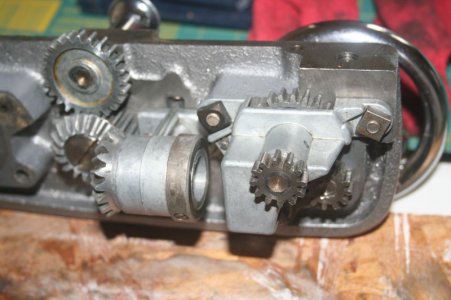
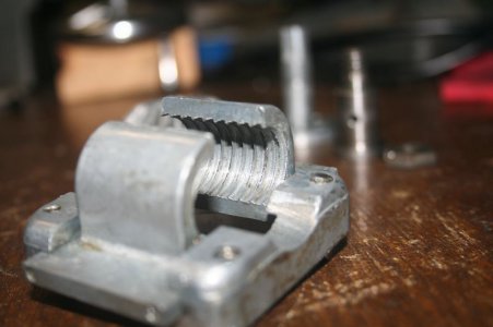
So I have been working on this lathe, regardless of the lack of updates here. I have been working the saddle rebuild and due to the small and many parts that are there I was taking it slow. Ran across some issues while doing this work. If you look closely at the 1/2 nut on the first photo, before cleaning, you can see the built up dried oil and swarf at the edge of the nut, where it closes together. When "closed" the nut wasn't really closed all the way and was really only grabbing just enough of the lead screw to work. This has caused extra wear on the 1/2 nut threads and lead screw, to the point that it and the lead screw will need replaced I think. It will be ok for cutting to size and auto feeding to get a cut done, but things like threading won't work anymore as the wear on this lead screw isn't linear so I couldn't get a thread that is the same the whole length of the screw. The areas closer to the headstock have obviously gotten more wear then farther away. I can see by eye this difference in the lead screw. Tried to get some good photos of the 1/2 nut, but had some issues with this.
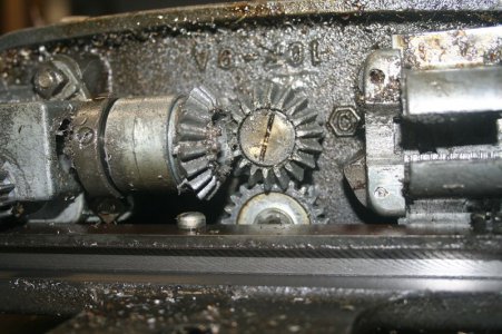
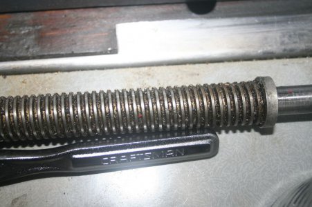
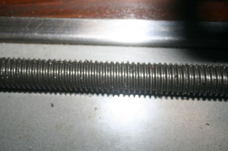
The last two photos of the lead screw show it off. Should have gotten photos of it cleaned as well, but I think it still shows the condition, especially the last one. The square threads are almost points near the left edge of the photo. Anyone done a lead screw replacement and put in acme thread rod? How did that work with the gears that were there and didn't get replaced?
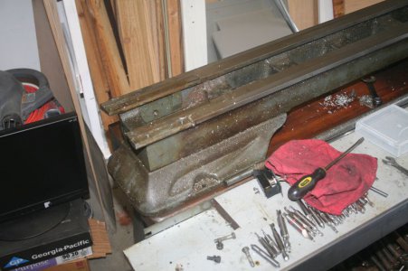
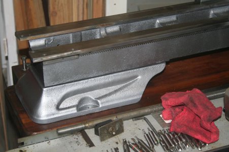
Other items that have been done are the cleaning and painting of the main body of the lathe. This has allowed me to start rebuilding and makes me feel like I am actually getting some work done. Some before and after pictures of this.
But I also have a problem and I am stuck on an issue with the tail stock and hoping for some pointers. The locking mechanism that locks the ram of the tail stock is binding when it is tightened and won't release the ram when it is loosened. The following is how this was setup when I got the lathe. The main screw that connects it all together is visually stretched. Also the center ares of this screw the threads are shot. Washers were added to the end so that different areas of the screw were used and there for only has but the barest of threads sticking out the top.
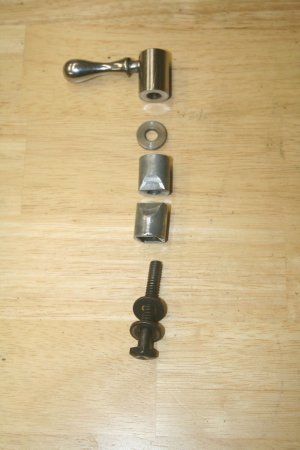
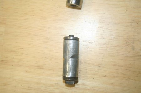
I replaced the screw with another one that had the same threading but had to grind the head down to get it to fit into the bottom piece of the locking barrel. This gives a much better thread spacing into the handle.
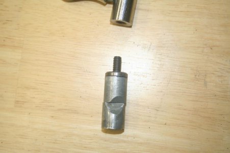
But the problem is that the bottom barrel piece that does part of the locking seems to be twisting and binding in the channel it works in. When I loosen it all this pieces stays bound up. Everything else can come free and be removed. This is the best photo I could get of it and you can sort of see that it is twisted against the ram body.
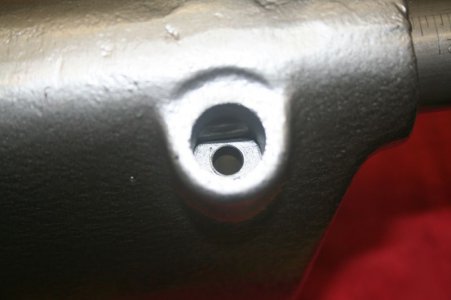
There aren't any burrs on the pieces or in the channel of the headstock. Everything moves nice and easy when installed and only bids once you twist the handle to tighten it. I don't feel like I am over tighten it, just enough to lock the ram from moving. That really seems to be only about a quarter to half turn to get done, once the slack in the threads is taken out. Any one else had this problem before or any ideas on how to deal with this?
Thanks in advance.
Philip


So I have been working on this lathe, regardless of the lack of updates here. I have been working the saddle rebuild and due to the small and many parts that are there I was taking it slow. Ran across some issues while doing this work. If you look closely at the 1/2 nut on the first photo, before cleaning, you can see the built up dried oil and swarf at the edge of the nut, where it closes together. When "closed" the nut wasn't really closed all the way and was really only grabbing just enough of the lead screw to work. This has caused extra wear on the 1/2 nut threads and lead screw, to the point that it and the lead screw will need replaced I think. It will be ok for cutting to size and auto feeding to get a cut done, but things like threading won't work anymore as the wear on this lead screw isn't linear so I couldn't get a thread that is the same the whole length of the screw. The areas closer to the headstock have obviously gotten more wear then farther away. I can see by eye this difference in the lead screw. Tried to get some good photos of the 1/2 nut, but had some issues with this.


The last two photos of the lead screw show it off. Should have gotten photos of it cleaned as well, but I think it still shows the condition, especially the last one. The square threads are almost points near the left edge of the photo. Anyone done a lead screw replacement and put in acme thread rod? How did that work with the gears that were there and didn't get replaced?
Other items that have been done are the cleaning and painting of the main body of the lathe. This has allowed me to start rebuilding and makes me feel like I am actually getting some work done. Some before and after pictures of this.


But I also have a problem and I am stuck on an issue with the tail stock and hoping for some pointers. The locking mechanism that locks the ram of the tail stock is binding when it is tightened and won't release the ram when it is loosened. The following is how this was setup when I got the lathe. The main screw that connects it all together is visually stretched. Also the center ares of this screw the threads are shot. Washers were added to the end so that different areas of the screw were used and there for only has but the barest of threads sticking out the top.


I replaced the screw with another one that had the same threading but had to grind the head down to get it to fit into the bottom piece of the locking barrel. This gives a much better thread spacing into the handle.

But the problem is that the bottom barrel piece that does part of the locking seems to be twisting and binding in the channel it works in. When I loosen it all this pieces stays bound up. Everything else can come free and be removed. This is the best photo I could get of it and you can sort of see that it is twisted against the ram body.

There aren't any burrs on the pieces or in the channel of the headstock. Everything moves nice and easy when installed and only bids once you twist the handle to tighten it. I don't feel like I am over tighten it, just enough to lock the ram from moving. That really seems to be only about a quarter to half turn to get done, once the slack in the threads is taken out. Any one else had this problem before or any ideas on how to deal with this?
Thanks in advance.
Philip


- Joined
- Apr 12, 2011
- Messages
- 3,573
Looks like you are coming along very nicely. Keep up the good work. It is amazing at what you'll find when tearing a machine down and what all really needs fixing.
To answer your question, I will ask one. Have you lubed the parts? If you haven't maybe a simple squirt of oil will do wonders.
To answer your question, I will ask one. Have you lubed the parts? If you haven't maybe a simple squirt of oil will do wonders.
- Joined
- Dec 12, 2011
- Messages
- 132
It's hard to tell from the pictures but it looks like the angle on the bottom part is shallower then the top part and might be "wedging" tightly to the ram instead of just pressing against it. Maybe whoever did the washer trick filed the angle ? If so maybe there is enough meat left to turn it 180 and grind the correct angle ?
HWF
HWF
- Joined
- Jun 11, 2013
- Messages
- 731
Looks like you are coming along very nicely. Keep up the good work. It is amazing at what you'll find when tearing a machine down and what all really needs fixing.
To answer your question, I will ask one. Have you lubed the parts? If you haven't maybe a simple squirt of oil will do wonders.
I had my tailstock binding alot too, lubed it up and it works great now.
Thanks for tips but it wasn't helped with oil on the pieces. It is still binding up and won't pop free. Top one is fine and comes "free" with no problems. I will see if I can adjust the bottom angle to match the top and see if that helps any. Wonder if there is other ways to get the ram locked?
On another note it seems I was mistaken and that the lead screw is already a acme thread. Was looking through the manual and it seems to be a acme 8 threads per inch screw. Totally missed that piece on other passes through the manual
Philip
On another note it seems I was mistaken and that the lead screw is already a acme thread. Was looking through the manual and it seems to be a acme 8 threads per inch screw. Totally missed that piece on other passes through the manual
Philip
- Joined
- Dec 25, 2011
- Messages
- 10,552
Phillip,
All Atlas lead screws are acme thread.
On the bottom tailstock ram lock piston, take a new condition fine flat file and run it across the bevel several times. My quess is that there may be a low spot on the face so that along the single contact line, the line isn't straight, allowing the piston to twist.
Robert D.
Hey all,
So this project isn't dead, or sadly competed just yet, and is still being worked on. It is amazing how your free time just disappears when you have a kid. Hope he is the best "shop accessory" every, but time will tell. In the mean time some updated photos of the headstock area, and a question.
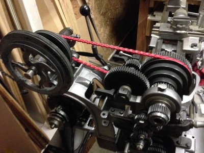
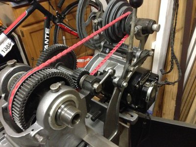
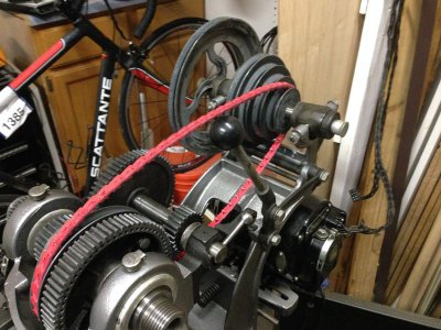
So I think I am at the point that if I had a motor I could power it on and get spinning things to spin and such. I have manually driven the lathe and everything seems to be working as expected at slow speed and is adjusted. I need to work on a lead screw and half nut replacement, but that won't keep me from using the lathe. But this leads me to my question. The motor that is on this lathe isn't the factory default one, I think. Last owner installed this motor with a custom drive controller circuit that allowed him to set the speed of the motor and thus the speed of the lathe, thus ignoring the quick change gear box. This speed controller is very old and I would like to change it out because of this and that he told me not to trust it when I bought the lathe. The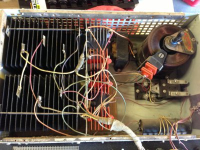
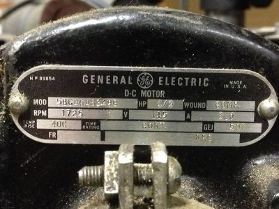
So I have a motor that was being run on DC power via this custom controller, but in looking at the name plate on the motor I think this is really a AC motor. My motor theory is low but I am aware that some motors can run on both AC or DC. My question is how can I confirm this motor will be ok on AC without plugging it in and finding out the hard way? Here is the spec plate from the motor.
Model # is 5BC46AB349C
Now I know the first response is going to be "Google it". I have tried and can't find any specs on this motor. If you can, please direct me, if I could find specs I would be fine.
Philip


So this project isn't dead, or sadly competed just yet, and is still being worked on. It is amazing how your free time just disappears when you have a kid. Hope he is the best "shop accessory" every, but time will tell. In the mean time some updated photos of the headstock area, and a question.


So I think I am at the point that if I had a motor I could power it on and get spinning things to spin and such. I have manually driven the lathe and everything seems to be working as expected at slow speed and is adjusted. I need to work on a lead screw and half nut replacement, but that won't keep me from using the lathe. But this leads me to my question. The motor that is on this lathe isn't the factory default one, I think. Last owner installed this motor with a custom drive controller circuit that allowed him to set the speed of the motor and thus the speed of the lathe, thus ignoring the quick change gear box. This speed controller is very old and I would like to change it out because of this and that he told me not to trust it when I bought the lathe. The
selenium rectifiers that he used are getting old and leaking is the issue there I believe.

So I have a motor that was being run on DC power via this custom controller, but in looking at the name plate on the motor I think this is really a AC motor. My motor theory is low but I am aware that some motors can run on both AC or DC. My question is how can I confirm this motor will be ok on AC without plugging it in and finding out the hard way? Here is the spec plate from the motor.

Model # is 5BC46AB349C
Now I know the first response is going to be "Google it". I have tried and can't find any specs on this motor. If you can, please direct me, if I could find specs I would be fine.
Philip


- Joined
- Jun 11, 2013
- Messages
- 731
Looks like a standard 1/3hp AC 115V motor from the nameplate. Wire it up and try it. If it works, use it. Those lathes came standard with a 1/3hp motor. Check out some of my vids if you want to see ones I worked on and them running.
btw, controlling the motor speed does not negate use of the quick change gear box. The gearbox is for changing feed rates to the leadscrew.
btw, controlling the motor speed does not negate use of the quick change gear box. The gearbox is for changing feed rates to the leadscrew.
- Joined
- Dec 25, 2011
- Messages
- 10,552
Steve,
NO NO NO! The nameplate quite clearly says D-C MOTOR. Plus it says that it is compound wound (COMP, which I won't bother to try to explain) which would also identify it as a DC motor. Further, the nameplate says 115 VDC at 3 amps full load. If you connected it directly to 120 VAC, you would quickly let all of the magic smoke out of it. The small rectifiers are undoubtedly for the shunt field. And the small transformer (although in the photo I can only see two wires) is probably for the field supply, although it could also be a filter choke.
Philip
The controller is a simple one, with no electronics in it (it is not electronically regulated). Looks like it consists of a motor starter relay, a Powerstat (that's a brand name, generic name is Variable Auto-transformer) for the main or armature variable supply, two rectifiers for the armature supply, and the much lighter fixed field supply. You are correct in being concerned about the selenium rectifiers. This wasn't known when they were first invented and commercialized but they turned out to have a 20 to 50 year typical shelf life. Even if I couldn't see one dangling wire in the photo, I definitely would not try to use the controller as is. Replacing the selenium's with silicon rectifiers is pretty trivial, except that you have to know what you are doing. If you lived close to Houston, you could bring it over here and we could convert it (and shrink it by half). But I wouldn't even attempt to try to tell you how to do it remotely.
On eBay tonight, I saw a few controllers for shunt wound DC motors but most are for either 230 VDC or for 1 HP or larger. However I only spent a few minutes looking. Most controllers are going to be for 90 VDC or 180 VDC permanent magnet motors. Which will not have a field supply. But a little looking should turn up one that will work.
However, 1/3 HP is a little light, even though that's what Atlas recommended in the 30's and 40's. To get the lathe running quickest, I would buy a 1/2 HP single-phase capacitor start motor. Later, you can if you like think about one of the other options.
Robert D.
