-
Welcome back Guest! Did you know you can mentor other members here at H-M? If not, please check out our Relaunch of Hobby Machinist Mentoring Program!
You are using an out of date browser. It may not display this or other websites correctly.
You should upgrade or use an alternative browser.
You should upgrade or use an alternative browser.
Atlas/Craftsman Serial Numbers and Bearing Dates (if applicable) For Database Entries
- Thread starter wa5cab
- Start date
- Joined
- Feb 1, 2020
- Messages
- 4
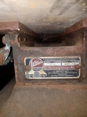
Hello! I just got my first lathe yesterday, and I spent the day trying to find any definite information, but I’m hitting a road block. To the best of my knowledge, it’s an Atlas 10F-28 with babbitt bearings and a 3/4” lead screw, made somewhere between 1937-1954, but it’s hard to find more than that. I’m interested in learning the story behind this magnificent machine, and I was hoping you guys and gals can help me with that! 
The lathe looks to be in amazing shape to my uneducated eye, but identifying information is difficult to find! There are no stamp marks on the bearings, and no label plate at the end of the bed, but I do have a “V 18004 S” stamped at the end of the bed and a “954” cast into the middle of the inside of the bed. Someone also engraved a “K186736” on the end of the bed as well, I’m not sure if that has any relevance but I thought I’d include it lol. I took a bunch of photos to see if there is any other info I needed to include in this post but didn’t lol. Is this enough to help get the full model number/SN, is there somewhere I didn’t look? Thanks in advance for all your help!
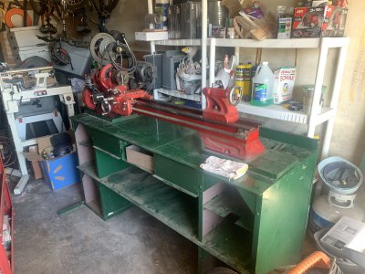
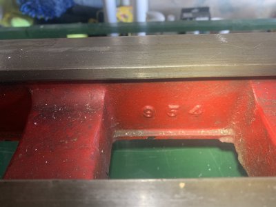
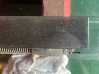
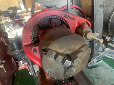
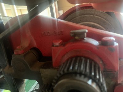
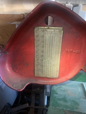
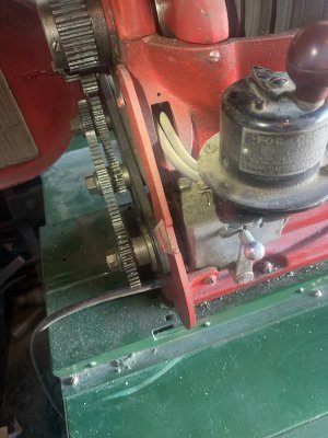
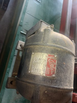
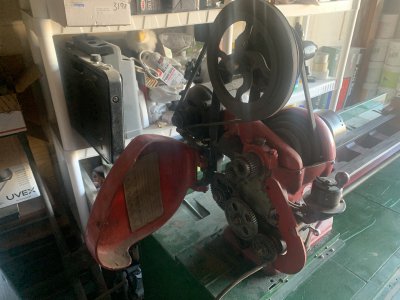
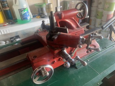
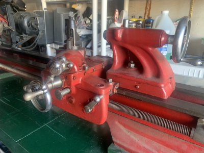
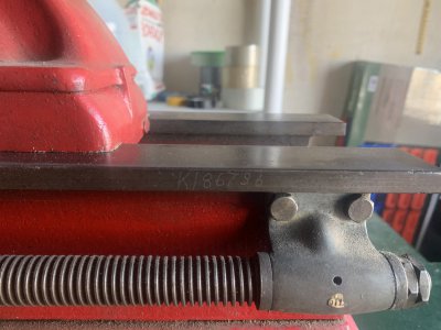
The lathe looks to be in amazing shape to my uneducated eye, but identifying information is difficult to find! There are no stamp marks on the bearings, and no label plate at the end of the bed, but I do have a “V 18004 S” stamped at the end of the bed and a “954” cast into the middle of the inside of the bed. Someone also engraved a “K186736” on the end of the bed as well, I’m not sure if that has any relevance but I thought I’d include it lol. I took a bunch of photos to see if there is any other info I needed to include in this post but didn’t lol. Is this enough to help get the full model number/SN, is there somewhere I didn’t look? Thanks in advance for all your help!


- Joined
- Dec 25, 2011
- Messages
- 10,552
OK. It is a 10F but the model number is "V" (for the Vertical countershaft that it came with) plus "54", a 2-digit number that is the nominal bed length. Choices are 36, 42, 48 and 54. Those happen to correspond to a nominal maximum distance between centers of 18", 24", 30" and 36". So your machine would be generically referred to as a 10x36. The 954 cast into the bed is the casting part number. And the first part of the finished part number. Which is probably 954B. You will find similar numbers cast into all of the cast iron parts plus almost all of the gears. Except that the cast Zamak parts had any suffix letters also cast in. This is true of the cast iron parts only if the casting changed when the revision letter suffix was added.
The serial number is 018004. No one still alive seems to know what the "S" stood for. It is found on at least some of the 10" and also on some of the early Craftsman 12". So it doesn't stand for "SEARS:.
The 10F Series was made from late 1938 until mid 1957. However, production of the babbit bearing models ceased in 1945. From the serial number, I would guess that your machine was made in 1940. During the period up to about 1952, the Timken bearings had a date engraved in both the cups and the cones. But no dates are found on the babbit bearings. The K186736 is probably the original owner's plant account or serial number. Up until about 1942, the serial number and one or two prefix letters and sometimes the suffix "S" was stamped into the top right end of the front way, and a name plate with the model number was affixed to the rear of the bed. Those are often missing but if you look, you should be able to find the two holes for the round head drive screws that attached it. The red paint is not original, and for whatever reason, most owners who repainted their machines removed the plate and screws and never bothered to re-install them. Around 1942, the nameplate moved to the right end of the bed and included the serial number. Again, many are missing. Which means that there is no way to roughly date the babbit bearing machines except for the dates engraved into the Timken bearings and a comparison of the serial numbers if known.
- Joined
- Feb 1, 2020
- Messages
- 4
Thanks for all the info! I really appreciate it!
As posted in the welcome section I thought I'd add this in here.
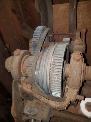
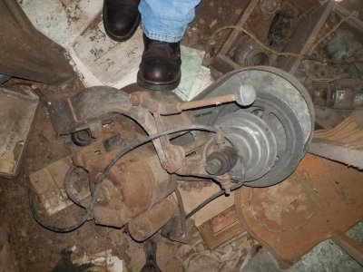
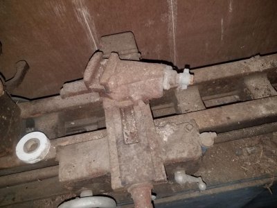
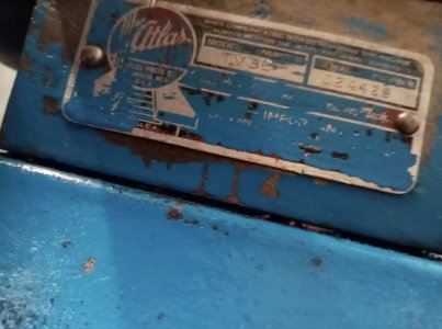
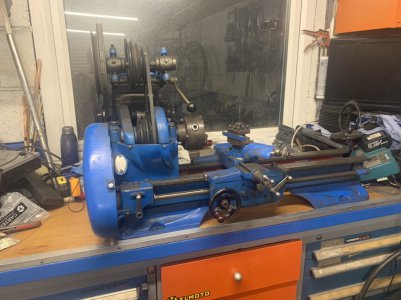
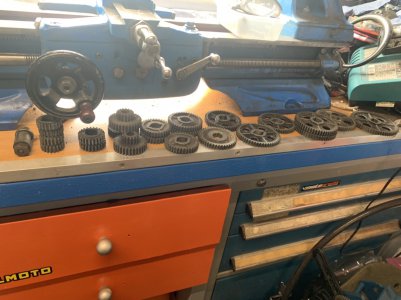
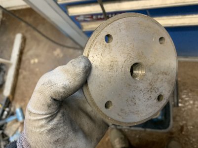
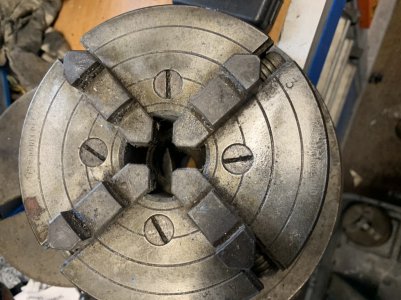
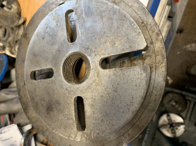
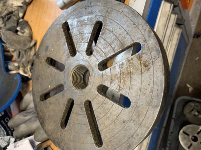
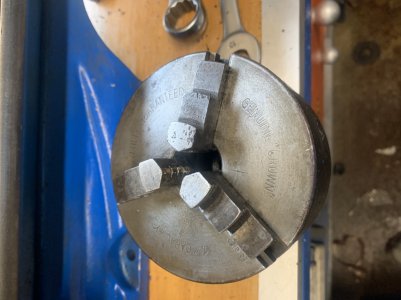
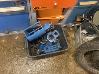
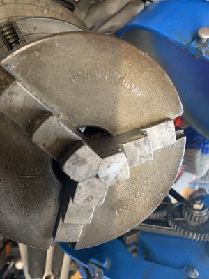
I just purchased an Atlas TV36 10F which came with a pile of change gears, 4 inch and 5 inch Crown 3 jaws, a 5 inch Bernerd 4 jaw, tail stock, face plate, travel steady, vertical 500A milling attachment and some sort of hang off gearbox which looks home made.
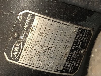
The backgear pin seems to be missing the detent ball and spring so the pin isn't properly located, the motor only has one pulley whereas the vertical wheel has two so I only have wheel A for speed selection. There is some lash maybe 10 degrees on the main carriage hand wheel but none on the cross travel. I'd love to find out how to adjust this (or repair it - I do have a spare lead screw) and I need to swap out some gears to slow down the traverse speed as it is way too quick when on power feed. I did try it in backgear mode when trying to part some aluminium but there seems no guts to the machine so I put the speed back up.
Any information on the origin of the machine would also be appreciated.
The power feeds work forward, backward and cross travel in both directions.
I found a page on Lathes.co.uk showing an invoice from April 1941 with the serial number 024444 and mine’s a TV36 with the serial 024428 so I’d assume is a similar vintage at 1941?.
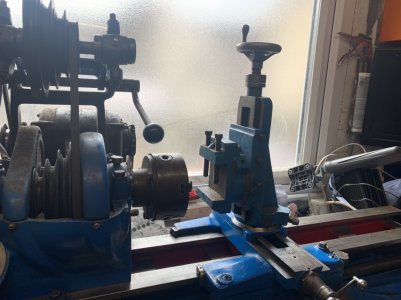
The centre of the indexable toolpost is about 5mm too high with a 1/2 inch tool although one face has been machined to take 12mm tools but I did acquire some smaller carbide tipped tools which arrived today. The spare lead screw looks to be standard.
The gears with the machine are as follows.
1 x gear carrier stub to mount 2 gears on(not sure what it’s called)
4 x 9101-20A
2 x 9101-24A
3 x transfer gears 16/32 compound gears
2 x 32 (1x thicker)
36A
2 x 40A
44
46
48A
52
54
54A
56A
64A
The home made gearbox has
40/18/30/18
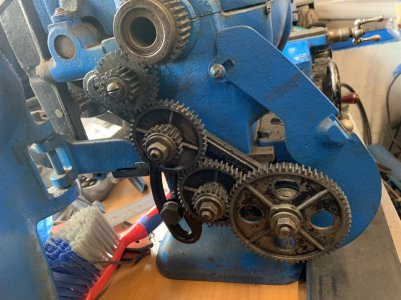
The lathe is running
64
20/44 compound
44
32/16 compound (16 not used)
And finally the 32 tooth head gear.
Any info would be appreciated.


Last edited:
- Joined
- Dec 25, 2011
- Messages
- 10,552
Exuptoy,
Welcome aboard. Your assumption that the machine was made just before 02444 is almost certainly valid. Especially as the machine was found in Britain. It appears to be fairly well equipped. And appears to be in good condition. The story on the gears is as follows. The basic part number for all of the change gears is the same, 9-101-nn. The "9" means that the original part first appeared on the Atlas 9" lathe. "101" is just an arbitrary sequence number assigned while the 9" was being designed. And "nn" is the gear tooth count. The original gears had a 3/8" hub length and a 3/8" face (the tooth length).
At the introduction of the Atlas 10F Series, the change gears were changed to a hub length of 1/2" with the face remaining at 3/8". This change is indicated by a suffix "A" to the part number. I have always assumed that the change was done to guarantee that even with misalignment and running clearance, the teeth on any gear in the Back position could never touch the teeth on any gear in the Front position, or vice versa. So you should go back through the gears that you have, as well as the studs and double-keyed bushings checking their length. If you have any gears with 1/2" hub length and 1/2" face, when you get the lathe working, you can modify them to be like the A-suffix gears and then they will be usable. If you have any gears with 3/8" hub length, the only way that you can use them would be to make two 1/16" thick double-keyway spacers for each 3/8" hub length gear. If you have any double-keyed bushings or shoulder bushings that are 3/4" long, those you cannot use. And although I don't know the length right off, the same goes for any studs that are too short. Probably you can sell those parts to someone with an earlier model 9", 10" or 12" Atlas or Atlas-built lathe.
The tool post that came with the lathe (the lantern-style one) was made to hold 3/8" square cutters. And if you later decide to add a quick-change tool post, the correct size for the 10" is the AXA, which also was made to use 3/8" tooling.
As you are already a Donor, you have access to Downloads. Go to the Atlas-Craftsman folder and to the manuals sub-folder below that and download the 1945 edition of the illustrated parts list. As far as I recall, the only significant change made to the 10F during the War was a modification to the headstock casting. So that and the motor switch mounting hardware should be the only part numbers that don't match your machine. We do have some earlier parts lists but the 1945 one is the first illustrated one, so it is better to use than the earlier section view and list of parts versions.
Also, running the machine in back gear should have greatly increased the available torque, not decreased it.
And although I didn't try to figure out what the change gears are set for, they are definitely not set for turning. Probably set for some fairly coarse pitch thread. Without even looking at the chart, if you replaced that 20T gear on front of the first gear after the Stud Gear with the largest gear still available and mesh it with the 16T instead of the 32T on the compound stud gear, you would cut the travel rate in half.
If your list of gears includes those on the machine, then you are missing a second 64T.
Last edited:
Thank you for that. There is a second 64T in my selection, one suffixed A. The list showing what the lathe is running is the gears currently fitted over and above the ones on the first part of the list. If I have a 3/8 / 3/8 gear could I just fit a 1/16th washer in between which is large enough to fit over the double keyway? Technically is cannot move anywhere.
I may try and set it up for metric threading and just be done with it.
It seems I am also missing the correct motor pulley as I only have speed selection A available.
I think the motor slowed down in backgear due to either a tired motor or slipping belts. Once I’ve got the cabinet made I will start to go through what I have and get the maintenance and adjustments set up.
- Joined
- Dec 25, 2011
- Messages
- 10,552
On the gears, if a gear has the Atlas part # cast into it of the form "9-101-nnA", the gear is from Atlas and is made for the 10F (or for the Craftsman 101.07403 and all later up through 1981) and is usable. If it has the number but does NOT have the "A" suffix, it is from Atlas but was made for the earlier 10" (or earlier Craftsman 12") and would be usable with two 1/16" spacers. If the gear does not have the part numbers but does have the correct ID configuration and hub length (1/2"), then it is usable but if the gear tooth face is also 1/2", then it will be usable if you face off 1/16" thickness from each side. After doing the facing, I would write the Atlas part number on one side for easier future selection.
Using a 1/16" thick spacer that has an ID large enough to fit over the double keys on the bushing probably won't work because I don't think there will be anything for it to fit against the is 3/8" thick. So it would just rattle around between the two gears and between the one gear and the shoulder on the shouldered bushing or between the washer and nut and the gear on the outside end of the stack.
On the motor question, motors do not "just get tired". Everything that can go wrong with a motor would affect it the same whether in back gear or direct drive.
For a 2-step motor pulley, in Downloads you will find an after-market drawing of the later pulley with the 5/8" bore. Several pulleys have been made by that drawing. If your motor happens to have an output shaft that is 1/2" in diameter instead of the later standard of 5/8" (0.625"), then use the drawing but make it with a 1/2" nominal ID and appropriate keyway. You could also get some RPM reduction by moving the single-step pulley on the motor shaft but you would also have to move the motor mounting position or use a longer belt. You could also find a single step pulley of the smaller diameter and to change speeds, also swap pulleys.

